®
INSTRUMENTS, LLC.
Product Catalog
Table of Contents
Electromagnetic Meters
FM676
.................................................................................................................................
6
FM658
.................................................................................................................................
9
FM626
...............................................................................................................................
13
FM656
...............................................................................................................................
17
FM656-HT
.........................................................................................................................
21
Propeller Meters
FM132
...............................................................................................................................
23
FM134
...............................................................................................................................
25
FM102
...............................................................................................................................
27
FM182 Direct
....................................................................................................................
30
FM182 Magnetic
...............................................................................................................
33
FM142
...............................................................................................................................
36
FM144
...............................................................................................................................
38
FM312
...............................................................................................................................
40
MainLine
...........................................................................................................................
42
FM112/114
.......................................................................................................................
47
Totalizers
...........................................................................................................................
49
FT190-111
.........................................................................................................................
55
Register Extension
............................................................................................................
60
Tubes and Saddles
............................................................................................................
61
Positive Displacement Meters
LSF
.....................................................................................................................................
66
Vortex Meters
FLM
...................................................................................................................................
69
Eggs Delta Pulse
................................................................................................................
72
Ex-DELTA
...........................................................................................................................
75
Products
FM676
FM658
FM626
FM656
FM656-HT
FM132
FM134
FM102
FM182 Direct
FM182 Magnetic
FM142
FM144
FM312
MainLine
FM112/114
FLM
Eggs Delta Pulse
Ex-DELTA
LSF
Totalizers
FT190-111
Register Extension
Tubes and Saddles
®
Electromagnetic Meters
®
INSTRUMENTS, LLC.
These meters excel in measuring the flow of conductive liquids
in full, closed pipes. With a wide variety of liners and electrodes,
including ‘Hot Tap’ removable style.
®
Technical Specifications
FM676
®
INSTRUMENTS, LLC.
Product Data Sheet
PDS-676
2026-07-31
BlueWater
Obstructionless
Electromagnetic Flowmeter
Description
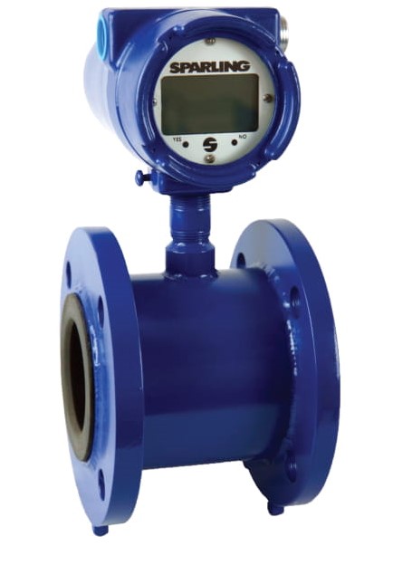
The Model 676 BlueWater electromagnetic
flowmeter is designed to measure the flow
of water (and other liquids) with full pipes
conditions. This model of flow meter is
ideally suited for irrigation as it is battery
operated, rugged, and easy to install and
configure.
The BlueWater stores all calibration and
flow information in a flash memory
eliminating the need for a backup battery
to store information and eliminating the
need to reprogram the meter if the module
is replaced or changed.
Principle of Operation
Sparling magnetic flowmeters are based on
Faraday's Law which states that the voltage
induced in a conductor moving through a
magnetic field is proportional to the
velocity of that conductor. Accuracy is
minimally affected by changes in
temperature, pressure, viscosity, or
conductivity.
Certified Accuracy
Each FM676 is 'wet-flow' calibrated in
Sparling's Primary Flow Lab traceable to
the National Institute of Standards and
Technology (NIST).
Applications
This model of flow meter is ideally suited
for irrigation as it is battery operated,
rugged, and easy to install and configure.
Features
•
Easily field programmable without
a factory service call
•
Long life battery, up to five years
•
Battery replacement requires no
tools
•
8V - 36V DC. When DC connected,
battery is backup.
•
Transmitter easily replaced in the
field without requiring removal of
the flow tube.
•
Stores total and calibration
information in a non-volatile flash
memory - no backup battery
required
•
Standard Pulse Output
•
Forward, reverse and net
totalization
•
Rotatable Modular Display
•
Empty pipe detection
•
Standard 1% Accuracy
•
Optional datalogger using standard
USB cable
•
Sizes available from 3" - 14"
®
INSTRUMENTS, LLC.
Installation
The meter can be installed in any orientation from vertical to horizontal.
A vertical installation, however, with liquid flowing up, is ideal as it
assures a full pipe.
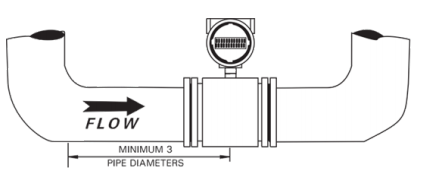
A minimum of three diameters of straight pipe length are required from
the center of the meter to normal obstructions to obtain specified
accuracies.
More straight approach should be provided after valves or multiple
elbows. Provide at least 10 diameters after expanders or laterals which
are of smaller diameter than the line size.
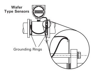
Grounding
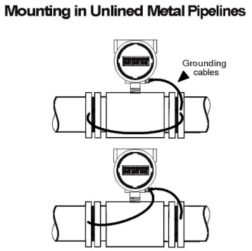
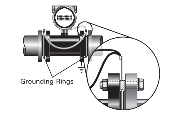
If the meter is installed in metal pipe, grounding rings are not required:
When installing in plastic or coated pipes, grounding rings are required:
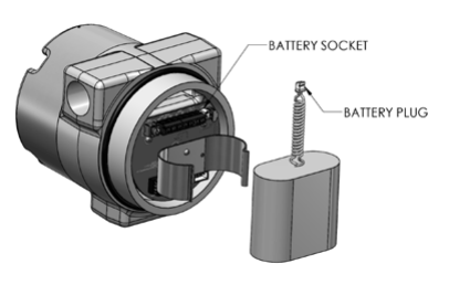
Battery
BlueWater has a long-life battery, up to five years. Changing the battery
is a straightforward operation, requiring no tools.
Standard Specifications
Accuracy:
±1% of flow (1fps - 33fps)
Power
Requirements:
7.2V 19Ah Battery and/or 8V - 36V DC. When DC
connected, battery is backup.
End
Connections:
ANSI B16.5 Cl 150
Process Temp:
-40°F - 180°F (-40°C - 82°C)
Storage Temp
Limits:
-40°F - 140°F (-40°C - 60°C)
Max. Working
Pressure:
150 psi
Ambient Temp:
-40°F - 140°F (-40°C - 60°C)
Wire Size:
Power: 14 AWG - 16 AWG, Pulse Output: 18
AWG
Power:
3 mW at lowest sample frequency
Minimum
Conductivity:
5 µ siemens
Velocity Range:
0fps - 33fps
Construction:
Metering Tube: 304 SS with welded ANSI
compliant carbon steel flanges
Liner: Polyurethane
Electrodes: 316 SS
Transmitter Enclosure: NEMA 4X
Electrical Rating: General Purpose
Output Signal:
Scaled Pulse 24VDC with selectable 12.5 / 25 /
50 / 100 ms on time, max.freq. 60Hz
How to order an FM676
Table 1: BaseModelNumber
FM676
-
BlueWater
Table 2: Size
03
-
3"
04
-
4"
06
-
6"
08
-
8"
10
-
10"
12
-
12"
14
-
14"
Table 3: Transmitter
0
-
Integral NEMA 4X encl.
Table 4: PowerSupply
1
-
Battery and DC Power
Table 5: Outputs
0
-
Pulse Output
Table 6: Datalogger
0
-
No Datalogger
1
-
Datalogger
Model
Size
Trans.
Power
Outputs
Data
FM676
03
0
1
0
0
®
INSTRUMENTS, LLC.
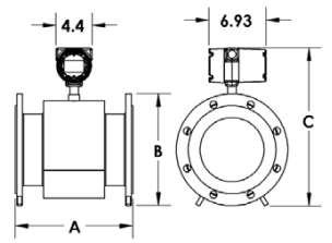
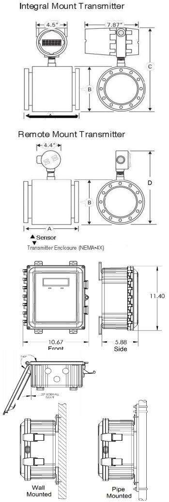
Flow Rates & Dimensions
Meter
Size
(in)
Weight
(lbs)
Dimensions (in)
Flow Rates (GPM)
A
B
C
1 fps
3 fps
33 fps
3.00
48.0
6.00
7.50
13.0
20.1
60.4
664
4.00
55.0
10.2
9.00
14.4
35.8
107
1180
6.00
75.0
12.3
11.0
17.0
88.1
264
2910
8.00
105
14.2
13.5
19.4
157
470
5170
10.0
155
18.2
16.0
22.6
245
734
8070
12.0
235
19.7
19.0
25.0
352
1060
11600
14.0
365
21.4
21.0
26.7
430
1290
14200
®
Technical Specifications
FM658
®
INSTRUMENTS, LLC.
Product Data Sheet
PDS-658
2026-07-31
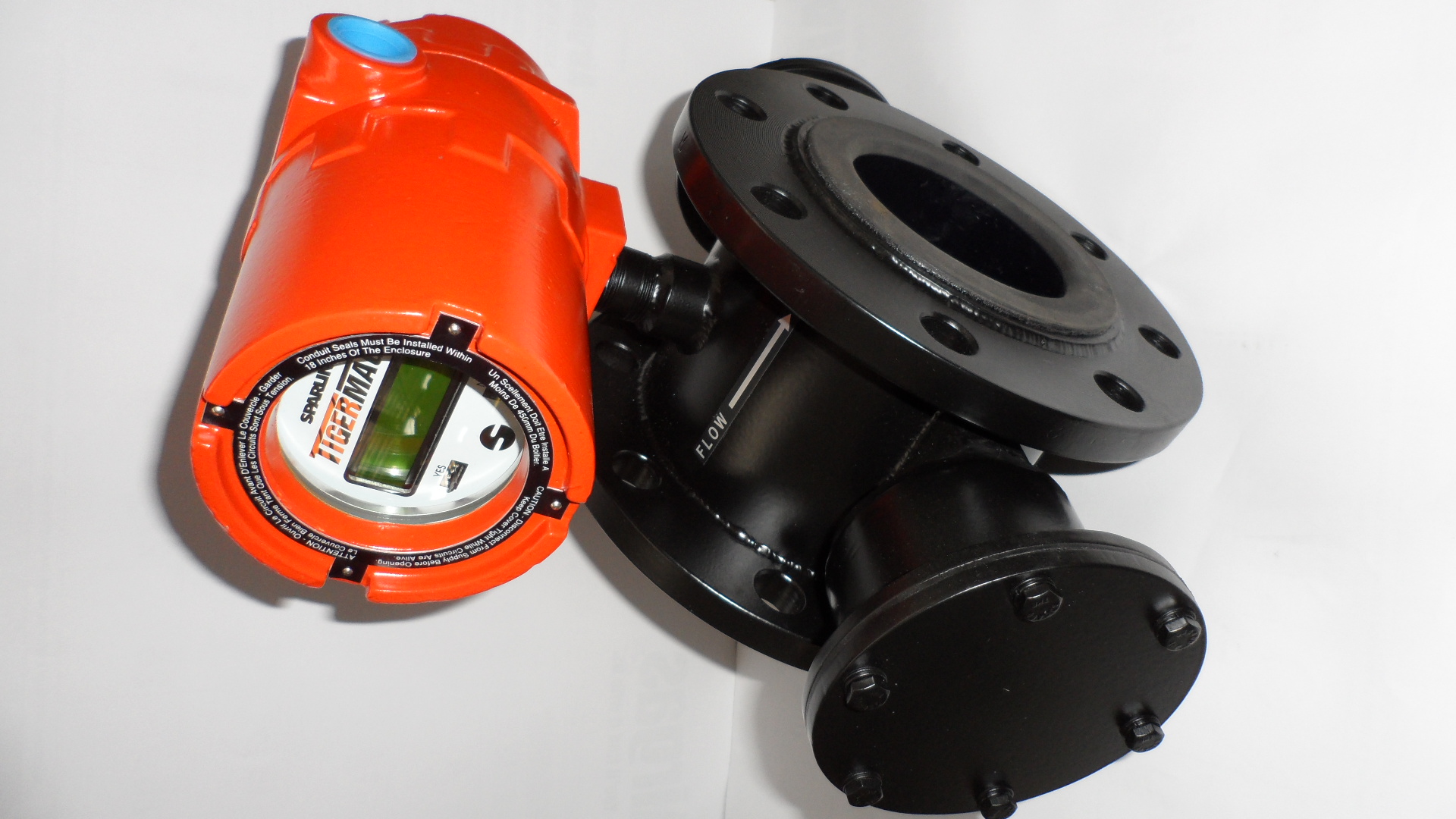
TigermagEP
Obstructionless
Electromagnetic Flowmeter
Description
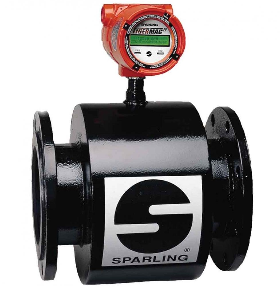
The TigermagEP is a microprocessor based
electromagnetic flowmeter designed to
measure the flow of conductive liquids in full
pipes. The sensor and transmitter are integral
and enclosed in a NEMA 7 explosion-proof
housing. The sensor housing is made of steel.
A wide variety of liner and electrodes are
available to tailor the meter to operate in many
processes.
The Tigermag's nonvolatile EEPROM memory
and circuitry eliminates the need for a
microprocessor backup battery. It is not
necessary to reprogram if the electronic
module is replaced or exchanged with
electronics from another size flowmeter.
Certified Accuracy
Each FM658 is 'wet-flow' calibrated in
Sparling's Primary Flow Lab traceable to the
National Institute of Standards and Technology
(NIST).
Principle of Operation
Sparling magnetic flowmeters are based on
Faraday's Law which states that the voltage
induced in a conductor moving through a
magnetic field is proportional to the velocity of
that conductor. Accuracy is minimally affected
by changes in temperature, pressure, viscosity,
or conductivity.
Applications
The Model FM658's high signal frequency
makes it ideally suited to applications with high
levels of inherent noise including: Process
Chemicals, Heavy Slurries, Polymers, Acids,
Alkalines, Sewage, Cooling Water. Nearly any
conductive liquid can be measured.
Features
•
Sampling frequency up to 100Hz for
accurate measurement of fluids with
high levels of inherent noise.
•
Forward & Reverse Totalization
•
Programmable high and low flow
alarms
•
Nonvolatile EEPROM Memory
•
Universal electronics module
compatability
•
Low Flow Cutoff
•
NEMA 4X/NEMA 7 explosion proof
enclosure
•
Accidental Submergence (NEMA 6/
IP67), Permanent Submergence
(NEMA 6P/IP68) and Direct Burial
Sensors available
•
Approvals Include: FM, CSA and NSF
61
•
Empty pipe detection
•
PZR - Positive Zero Return
•
Standard 0.5% Accuracy
•
Sizes available from 0.1" - 72"
®
INSTRUMENTS, LLC.
Installation
The meter must be mounted at a point in the line which is always full of
process liquid under flowing conditions.
A minimum of three diameters of straight pipe length are required from
the center of the meter to normal obstructions to obtain specified
accuracies.
The meter may be equipped with the following flanges: ANSI 150 or
300#, AWWA, DIN, PN 10 or 16, JIS or British Standard.
Nonvolatile EEPROM Memory
A backup battery is not required and there is no need to reprogram if
the electronics module is replaced or exchanged. Meter identification
(tube ID, serial number, K, offeset, etc.) is stored on an EEPROM chip
independent of transmitter electronics. The EEPROM chip has lifetime
data retention.
Empty pipe detection
The Sparling TigermagEP is designed to detect absence or inadequate
volume of process fluid in the pipe and will hold the output signal to
4mA or zero. This feature does not require any hard wiring as it is a
software selection. One of the most important values of this feature is
that it prevents false totalization possible with other meters under
partially filled pipe conditions
Ease of Communications
The TigermagEP is programmable with Mag-Command, Modbus or Hart
Protocol. 4-20mA, RS-232 or RS-485 outputs give you flexibility when
interfacing with your distrubuted control system.
Hi-Z Circuitry
The Sparling TigermagEP provides superior performance in liquids which
tend to deposit nonconductive coatings. Hi-Z circuitry produces a high
input impedance to the transmitter's preamplifier (1x10
12
Ohms). The
impedance of the coating is negligible as compared to the impedance of
the receiving instrument. The voltage drop across the electrode coating
is also negligible eliminating the need for electrode cleaners.
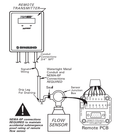
Remote Mounted Transmitter
Remote mounting of the transmitter is required when pipe vibration is
excessive, when flooding is possible or where high termperature
conditions exist (over 100°F).
The TigermagEP remote transmitter is housed in a NEMA-4X enclosure
and features a larger sized (8mm) 16 digit 2-line backlit display. All
power, coil, and elctrode connections are made within the transmitter
enclosure and junction box. The meter is programmed using
Mag-Command. Hall-effect switches which are energized from outside
the enclosure. The enclosure can be wall mounted. An optional bracket
for pipe mounting is available.
Two flow alarms
Fault alarms can be configured with alarm set points between 0-99% of
flow for each alarm. Open collector output turns on above programmed
set point.
Grounding
The use of grounding rings is recommended to ensure accuracy.
Grounding rings are required if adjacent piping is lined or
nonconductive. Pump noise or excessive RF should be minimized to
achieve highest accuracy.
PZR - Positive Zero Return
An electronic circuit is activated by an external contact closure when
lines go empty or when a pump or valve is shut down, indicating to the
meter that it should drive the output signal to 4mA or 0.
Removable Electrodes
Two configurations of removable electrodes are available in sizes of 6"
or greater for all FM656 meters. The first configuration allows removal
of the electrode after the line has been depressurized and drained.
Removal is performed with an 11/32" nut driver and a 3/4" socket
wrench.
The second is the "hot-tap" electrode which allows electrode
replacement while the system is still under pressure without disturbing
the process flow. Removal can be easily performed with a phillips
screwdriver and a crescent wrench. Special locking catches were
designed to prevent high pressure accidents during electrode removal.
The shut-off valve must be closed before the electrode may be
removed.
®
INSTRUMENTS, LLC.
Flow Rates & Dimensions
Meter Size
(in)
Dimensions (in)
Flow Rates (GPM)
A
B
C
D
150#
300#
150#
300#
150#
300#
150#
300#
1 fps
3 fps
33 fps
0.100
4.00
4.00
3.50
3.75
9.50
9.62
9.25
9.30
0.0382
0.115
1.26
0.250
4.00
4.00
3.50
3.75
9.50
9.62
9.25
9.30
0.153
0.459
5.05
0.375
4.00
4.00
3.50
3.75
9.50
9.62
9.25
9.30
0.342
1.03
11.3
0.500
4.00
4.00
3.50
3.75
9.50
9.62
9.25
9.30
0.568
1.71
18.8
1.00
4.00
4.00
4.25
4.88
10.2
10.5
9.94
10.2
2.02
6.07
66.7
1.50
4.00
4.00
5.00
5.12
10.9
11.4
10.6
11.2
5.29
15.9
174
2.00
4.00
4.00
6.00
6.50
11.7
11.9
11.4
11.6
9.18
27.5
303
2.50
6.00
6.00
7.00
7.50
12.6
12.9
11.6
11.9
13.1
39.2
431
3.00
6.00
6.00
7.50
8.25
13.0
13.4
12.8
13.2
20.1
60.4
664
4.00
6.00
6.00
9.00
10.0
14.4
14.9
14.1
14.6
35.8
107
1180
6.00
13.4
14.9
11.0
12.5
17.0
17.8
16.8
17.5
88.1
264
2910
8.00
13.4
15.4
13.5
14.2
19.4
19.8
19.1
19.5
157
470
5170
10.0
18.1
20.6
16.0
17.5
22.6
23.3
22.3
23.1
245
734
8070
12.0
19.4
21.8
19.0
20.5
25.0
25.8
24.8
25.5
352
1060
11600
14.0
21.4
23.8
21.0
23.0
26.7
27.7
26.4
27.4
430
1290
14200
16.0
23.4
25.9
23.5
25.5
29.0
30.0
28.7
29.7
569
1710
18800
18.0
27.2
29.9
25.0
28.0
31.1
32.6
34.9
32.4
728
2180
24000
20.0
27.6
30.4
27.5
30.5
33.4
34.9
33.1
34.6
907
2720
29900
24.0
32.8
35.8
32.0
36.0
37.4
39.4
37.2
39.2
1310
3920
43100
30.0
43.5
46.6
38.8
43.0
43.7
45.9
43.5
45.6
2070
6220
68400
36.0
47.8
50.9
46.0
50.0
50.2
52.2
50.0
52.0
3010
9040
99500
42.0
51.8
55.1
53.0
57.0
56.9
58.9
56.6
58.6
4110
12300
136000
48.0
51.8
55.4
59.5
65.0
63.0
65.8
62.8
65.5
5400
16200
178000
54.0
53.5
*
66.2
*
69.9
*
69.6
*
6810
20400
225000
60.0
65.5
*
73.0
*
76.8
*
76.5
*
8810
26400
291000
66.0
65.5
*
80.0
*
83.8
*
83.5
*
10700
32000
352000
72.0
72.8
*
86.5
*
90.0
*
89.8
*
12700
38100
419000
Dimensions for flanges. Allow 0.125" to 0.25" for lining thickness/Dimensions C & D ±0.125"
Flow Rates: 0.25" - 4" flow rates are for FEP/PTFE, Poly, and HR liners. Ceramic sensor flow rates differ slightly. Please see
PDS-626
for ceramic sensor flow rates for 0.25" - 4"
How to order a TigermagEP
Table 1: BaseModelNumber
FM658
-
Flanged, Blind, Magnetic Flowmeter
Table 2: Size
AA
-
0.1"
OA
-
0.25"
OB
-
0.375"
OD
-
0.5"
OF
-
1"
OG
-
1.5"
02
-
2"
OH
-
2.5"
03
-
3"
04
-
4"
06
-
6"
08
-
8"
10
-
10"
12
-
12"
14
-
14"
16
-
16"
18
-
18"
20
-
20"
24
-
24"
30
-
30"
etc.
Table 3: LinerMaterial
1
-
Hard Rubber (1-72")
5
-
Polyurethane (2-72")
6
-
Ceramic
1
(0.1-4")
8
-
FEP (0.25-48")
A
-
Polyurethane for potable water (2-72")
Table 4: ElectrodeMaterial
1
-
316 SS
2
-
Hastelloy C
3
-
316 SS BN
4
-
Titanium
5
-
Tantalum
6
-
Fused Pt: Ceramic Liners
7
-
Platinum: Other Liners
8
-
Zirconium
9
-
Monel
0
-
Tungsten Carbide
B
-
HastC BN
D
-
Titanium BN
E
-
Tantalum BN
G
-
Platinum BN
H
-
Zirconium BN
I
-
Monel BN
Table 5: FlangeRating
1
-
AWWA Cl (150#)
3
-
AWWA Cl (300#)
A
-
ANSI B16.5 Cl 150
B
-
ANSI B16.5 Cl 300
C
-
ANSI B16.5 Cl 400
D
-
ANSI B16.5 Cl 500
S
-
Tri-Clamp (Sanitary)
Table 6: Transmitter
F
-
Integral NEMA 4X encl.
G
-
Integral NEMA 4X encl. Battery Operated
0
-
Integral NEMA 7 encl.
1
-
Remote NEMA 7 encl. encl., 15ft Cable
2
-
Remote NEMA 7 encl. encl., 15ft Cable, Perm. Sub
3
-
Remote NEMA 7 encl. encl., 15ft Cable, Acc. Sub
4
-
Remote NEMA 7 encl. encl., 15ft Cable, Direct Burial
5
-
Remote NEMA 4X encl. encl., 15ft Cable
6
-
Remote NEMA 4X encl. encl., 15ft Cable, Acc. Sub
7
-
Remote NEMA 4X encl. encl., 15ft Cable, Direct Burial
8
-
Remote NEMA 4X encl. encl., 15ft Cable, Perm. Sub
Table 7: PowerCube
0
-
77-265 VAC
1
-
12-60 VDC
Table 8: Options
HART, Modbus, RS485, RS232
High Temperature Coils (Req Over 266°F)
Hot Tap Removable Electrodes (4"+)
Removable Electrodes (4"+)
Add Cable (15ft - 300ft)
Relay for Fault and Flow Alarms
Model
Size
Liner
Electrode
Flange
Transmitter
Power
FM658
24
8
7
A
5
1
1. Ceramic Liner not available in the following sizes: 0.375" or 2.5"
3. FM approval is up to 120V
®
INSTRUMENTS, LLC.
Standard Specifications
Accuracy:
0.1" - 0.25": ±1% of flow (1fps - 33fps)
0.5" - 8": ±0.5% of flow (1fps - 33fps)
Temp Effect:
±0.025% FS/°C
Full Scale Ranges:
From 0fps - 3fps to 0fps - 33fps
Repeatability:
±0.1% of full scale
Electrodes:
316 SS Standard (others available)
Liner:
Hard Rubber, Polyurethane, Ceramic, FEP/PTFE, Polyurethane liner for potable water certified to NSF61
Outputs:
1)
Isolated analog 4mA - 20mA DC into 800 Ohms
2)
Scaled Pulse 24VDC with selectable 12.5 / 25 / 50 / 100 ms on time, max.freq. 60Hz
3)
0Hz - 1000Hz Freq., for 0%-100% of flow rate, 15VDC
4)
Two flow alarms
5)
Fault, with open collector
6)
RS232 communication
7)
Flow direction with open collector
8)
Positive Zero Return (PZR) for external relay contacts. Outputs 2 and 3 can be open collector if
required.
9)
HART Protocol Available
10)
Modbus Protocol Available
Mag-Command™:
Selection and change of meter parameters by magnetic probe without opening the enclosure.
Display:
2-Line, 16 Digit alphanumeric backlit display (rate and total). Modular, rotatable 360° in 90° increments
Min Velocity
1
:
0.3fps
Power Requirements:
77-265VAC / 12-60VDC
Power Consumption:
Less than 20 W
Enclosures:
Cast alumnium epoxy coated. Integral NEMA 7 encl. or Remote NEMA 4X encl.
Sensor Housing:
Fabricated steel, epoxy coated
Preamp Impedance:
1x10
12
Ohms minimum
Amb. Temp:
-20°F - 140°F (-29°C - 60°C) Display darkens over 158°F (70°C)
End Connections:
150# or 300#
Sensor Tube:
304 Stainless Steel
Process Temp:
Integral Mount:
•
Hard Rubber, Neoprene, Polyurethane, Food Grade Polyurethane: -40°F - 180°F
•
TEF, Ceramic: -40°F - 212°F
Remote Mount (opt):
•
TEF, Ceramic: -40°F - 266°F
High Temperature Coils (opt):
•
TEF: -40°F - 300°F
•
Ceramic: -40°F - 420°F
Selectable Damping:
0-99 Seconds
Minimum Conductivity:
5 µ siemens
Low Flow Cutoff:
Selectable 0-9% of full scale
1
Minimum Velocity is the lowest velocity the meter will show a reading. Accuracy, however, is subject to the limits above.
Model FM658 Specification available on request
®
Technical Specifications
FM626
®
INSTRUMENTS, LLC.
Product Data Sheet
PDS-626
2026-07-31
TigermagEP
Obstructionless
Electromagnetic Flowmeter
Description
The TigermagEP is a microprocessor based
electromagnetic flowmeter designed to
measure the flow of conductive liquids in full
pipes. The sensor and transmitter are integral
and enclosed in a NEMA 7 explosion-proof
housing. The sensor housing is made of steel.
A wide variety of liner and electrodes are
available to tailor the meter to operate in many
processes.
The Tigermag's nonvolatile EEPROM memory
and circuitry eliminates the need for a
microprocessor backup battery. It is not
necessary to reprogram if the electronic
module is replaced or exchanged with
electronics from another size flowmeter.
Certified Accuracy
Each FM626 is 'wet-flow' calibrated in
Sparling's Primary Flow Lab traceable to the
National Institute of Standards and Technology
(NIST).
Principle of Operation
Sparling magnetic flowmeters are based on
Faraday's Law which states that the voltage
induced in a conductor moving through a
magnetic field is proportional to the velocity of
that conductor. Accuracy is minimally affected
by changes in temperature, pressure, viscosity,
or conductivity.
Applications
The Model FM626's high signal frequency
makes it ideally suited to applications with high
levels of inherent noise including: Process
Chemicals, Heavy Slurries, Polymers, Acids,
Alkalines, Sewage, Cooling Water. Nearly any
conductive liquid can be measured.
Features
•
Sampling frequency up to 100Hz for
accurate measurement of fluids with
high levels of inherent noise.
•
Forward, reverse and net totalization
•
Programmable high and low flow
alarms
•
Nonvolatile EEPROM Memory
•
Universal electronics module
compatability
•
2-Line, 16 character backlit display
•
Programming made easy with
Mag-Command™
•
Low Flow Cutoff
•
NEMA 4X/NEMA 7 explosion proof
enclosure
•
Accidental Submergence (NEMA 6/
IP67), Permanent Submergence
(NEMA 6P/IP68) and Direct Burial
Sensors available
•
Approvals Include: FM, CSA and NSF
61
•
Rotatable Modular Display
•
Empty pipe detection
•
PZR - Positive Zero Return
•
Standard 0.5% Accuracy
•
Sizes available from 0.1" - 8"
®
INSTRUMENTS, LLC.
Installation
The meter must be mounted at a point in the line which is always full of
process liquid under flowing conditions.
A minimum of three diameters of straight pipe length are required from
the center of the meter to normal obstructions to obtain specified
accuracies.
The meter can be installed between the following flanges: ANSI 150 or
300#, AWWA, DIN, PN 10 or 16, JIS or British Standard.
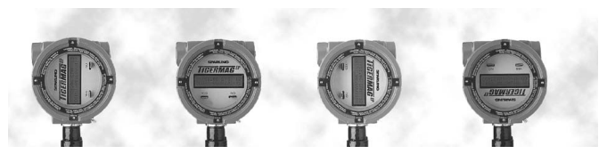
Easy To Read Backlit Rotatable Display
The 16 character, 2-line backlit Totalizer display is rotatable 360° in 90°
increments ensuring easy reading in any orientation.
Nonvolatile EEPROM Memory
A backup battery is not required and there is no need to reprogram if
the electronics module is replaced or exchanged. Meter identification
(tube ID, serial number, K, offeset, etc.) is stored on an EEPROM chip
independent of transmitter electronics. The EEPROM chip has lifetime
data retention.
Empty pipe detection
The Sparling TigermagEP is designed to detect absence or inadequate
volume of process fluid in the pipe and will hold the output signal to
4mA or zero. This feature does not require any hard wiring as it is a
software selection. One of the most important values of this feature is
that it prevents false totalization possible with other meters under
partially filled pipe conditions
Ease of Communications
The TigermagEP is programmable with Mag-Command, Modbus or Hart
Protocol. 4-20mA, RS-232 or RS-485 outputs give you flexibility when
interfacing with your distrubuted control system.
Hi-Z Circuitry
The Sparling TigermagEP provides superior performance in liquids which
tend to deposit nonconductive coatings. Hi-Z circuitry produces a high
input impedance to the transmitter's preamplifier (1x10
12
Ohms). The
impedance of the coating is negligible as compared to the impedance of
the receiving instrument. The voltage drop across the electrode coating
is also negligible eliminating the need for electrode cleaners.
Diagnostics
The TigermagEP's unique diagnostic functions eliminate the need for a
technician to carry test equipment or open the housing. Current ramp,
complete coil check and true front-end input simulator may be
activated in Mag-Command without opening the enclosure. This is
especially important in hazardous areas and aggressive plant
environments.
Two flow alarms
Fault alarms can be configured with alarm set points between 0-99% of
flow for each alarm. Open collector output turns on above programmed
set point.
Grounding
The use of grounding rings is recommended to ensure accuracy.
Grounding rings are required if adjacent piping is lined or
nonconductive. Pump noise or excessive RF should be minimized to
achieve highest accuracy.
PZR - Positive Zero Return
An electronic circuit is activated by an external contact closure when
lines go empty or when a pump or valve is shut down, indicating to the
meter that it should drive the output signal to 4mA or 0.
Remote Mounted Transmitter
Remote mounting of the transmitter is required when pipe vibration is
excessive, when flooding is possible or where high termperature
conditions exist (over 100°F).
The TigermagEP remote transmitter is housed in a NEMA-4X enclosure
and features a larger sized (8mm) 16 digit 2-line backlit display. All
power, coil, and elctrode connections are made within the transmitter
enclosure and junction box. The meter is programmed using
Mag-Command. Hall-effect switches which are energized from outside
the enclosure. The enclosure can be wall mounted. An optional bracket
for pipe mounting is available.
®
INSTRUMENTS, LLC.
Flow Rates & Dimensions
Meter
Size
(in)
Mating
Flange
(in)
Dimensions (in)
Flow Rates (GPM)
Ceramic
Poly / FEP / HR
A
B
C
D
1 fps
3 fps
33 fps
1 fps
3 fps
33 fps
0.100
0.500
4.00
2.31
8.97
5.26
0.0382
0.115
1.26
*
*
*
0.250
0.500
4.00
2.31
8.97
5.26
0.213
0.639
7.03
0.153
0.459
5.05
0.375
0.500
4.00
2.31
8.97
5.26
*
*
*
0.342
1.03
11.3
0.500
0.500
4.00
2.31
8.97
5.26
0.487
1.46
16.1
0.568
1.71
18.8
1.00
1.00
4.00
2.92
9.60
5.87
1.61
4.84
53.2
2.02
6.07
66.7
1.50
1.50
4.00
3.62
10.2
6.57
4.39
13.2
145
5.29
15.9
174
2.00
2.00
4.00
4.12
10.8
7.07
6.99
21.0
231
9.18
27.5
303
2.50
2.50
6.00
4.62
11.4
10.0
*
*
*
13.1
39.2
431
3.00
3.00
6.00
5.70
12.0
8.65
20.6
61.7
679
20.1
60.4
664
4.00
4.00
6.00
6.60
13.2
9.55
35.3
106
1170
35.8
107
1180
6.00
6.00
8.00
8.76
15.5
14.2
*
*
*
88.1
264
2910
8.00
8.00
8.00
10.9
17.5
16.5
*
*
*
157
470
5170
Allow 0.125" to 0.25" for lining thickness/Dimensions C & D ±0.125"
How to order a TigermagEP
Table 1: BaseModelNumber
FM626
-
Flangeless Tigermag
Table 2: Size
AA
-
0.1"
OA
-
0.25"
OB
-
0.375"
OD
-
0.5"
OF
-
1"
OG
-
1.5"
02
-
2"
OH
-
2.5"
03
-
3"
04
-
4"
06
-
6"
08
-
8"
Table 3: LinerMaterial
1
-
Hard Rubber (1-8")
5
-
Polyurethane (2-8")
6
-
Ceramic
1
(0.1-4")
8
-
FEP (0.25-8")
A
-
Polyurethane for potable water (2-8")
Table 4: ElectrodeMaterial
1
-
316 SS
2
-
Hastelloy C
3
-
316 SS BN
4
-
Titanium
5
-
Tantalum
6
-
Fused Pt: Ceramic Liners
7
-
Platinum: Other Liners
8
-
Zirconium
9
-
Monel
0
-
Tungsten Carbide
B
-
HastC BN
D
-
Titanium BN
E
-
Tantalum BN
G
-
Platinum BN
H
-
Zirconium BN
I
-
Monel BN
Table 5: MountingBolts
0
-
Carbon Steel, Zn Plated
1
-
None Required
2
-
Stainless Steel (304)
Table 6: Transmitter
F
-
Integral NEMA 4X encl.
G
-
Integral NEMA 4X encl. Battery Operated
0
-
Integral NEMA 7 encl.
1
-
Remote NEMA 7 encl. encl., 15ft Cable
2
-
Remote NEMA 7 encl. encl., 15ft Cable, Perm. Sub
3
-
Remote NEMA 7 encl. encl., 15ft Cable, Acc. Sub
4
-
Remote NEMA 7 encl. encl., 15ft Cable, Direct Burial
5
-
Remote NEMA 4X encl. encl., 15ft Cable
6
-
Remote NEMA 4X encl. encl., 15ft Cable, Acc. Sub
7
-
Remote NEMA 4X encl. encl., 15ft Cable, Direct Burial
8
-
Remote NEMA 4X encl. encl., 15ft Cable, Perm. Sub
Table 7: PowerCube
0
-
77-265 VAC
1
-
12-60 VDC
Table 8: Options
HART, Modbus, RS485, RS232
High Temperature Coils (Req Over 266°F)
Hot Tap Removable Electrodes (4"+)
Removable Electrodes (4"+)
Add Cable (15ft - 300ft)
Relay for Fault and Flow Alarms
Model
Size
Liner
Electrode
Mounting
Transmitter
Power
FM626
AA
6
1
0
F
0
1. Ceramic Liner not available in the following sizes: 0.375" or 2.5"
3. FM approval is up to 120V
Note: Remote enclosure shown for meters shipped after
July '16
Please call factory for dimensions shipped
July '16
and before
®
INSTRUMENTS, LLC.
Standard Specifications
Accuracy:
0.1" - 0.25": ±1% of flow (1fps - 33fps)
0.5" - 8": ±0.5% of flow (1fps - 33fps)
Temp Effect:
±0.025% FS/°C
Full Scale Ranges:
From 0fps - 3fps to 0fps - 33fps
Repeatability:
±0.1% of full scale
Electrodes:
316 SS Standard (others available)
Liner:
Hard Rubber, Polyurethane, Ceramic, FEP/PTFE, Polyurethane liner for potable water certified to NSF61
Outputs:
1)
Isolated analog 4mA - 20mA DC into 800 Ohms
2)
Scaled Pulse 24VDC with selectable 12.5 / 25 / 50 / 100 ms on time, max.freq. 60Hz
3)
0Hz - 1000Hz Freq., for 0%-100% of flow rate, 15VDC
4)
Two flow alarms
5)
Fault, with open collector
6)
RS232 communication
7)
Flow direction with open collector
8)
Positive Zero Return (PZR) for external relay contacts. Outputs 2 and 3 can be open collector if
required.
9)
HART Protocol Available
10)
Modbus Protocol Available
Mag-Command™:
Selection and change of meter parameters by magnetic probe without opening the enclosure.
Display:
2-Line, 16 Digit alphanumeric backlit display (rate and total). Modular, rotatable 360° in 90° increments
Min Velocity
1
:
0.3fps
Power Requirements:
77-265VAC / 12-60VDC
Power Consumption:
Less than 20 W
Enclosures:
Cast alumnium epoxy coated. Integral NEMA 7 encl. or Remote NEMA 4X encl.
Sensor Housing:
Fabricated steel, epoxy coated
Preamp Impedance:
1x10
12
Ohms minimum
Amb. Temp:
-20°F - 140°F (-29°C - 60°C) Display darkens over 158°F (70°C)
End Connections:
150# or 300#
Sensor Tube:
304 Stainless Steel
Process Temp:
Integral Mount:
•
Hard Rubber, Neoprene, Polyurethane, Food Grade Polyurethane: -40°F - 180°F
•
TEF, Ceramic: -40°F - 212°F
Remote Mount (opt):
•
TEF, Ceramic: -40°F - 266°F
High Temperature Coils (opt):
•
TEF: -40°F - 300°F
•
Ceramic: -40°F - 420°F
Selectable Damping:
0-99 Seconds
Minimum Conductivity:
5 µ siemens
Low Flow Cutoff:
Selectable 0-9% of full scale
1
Minimum Velocity is the lowest velocity the meter will show a reading. Accuracy, however, is subject to the limits above.
Model FM626 Specification available on request
®
Technical Specifications
FM656
®
INSTRUMENTS, LLC.
Product Data Sheet
PDS-656
2026-07-31
TigermagEP
Obstructionless
Electromagnetic Flowmeter
Description
The TigermagEP is a microprocessor based
electromagnetic flowmeter designed to
measure the flow of conductive liquids in full
pipes. The sensor and transmitter are integral
and enclosed in a NEMA 7 explosion-proof
housing. The sensor housing is made of steel.
A wide variety of liner and electrodes are
available to tailor the meter to operate in many
processes.
The Tigermag's nonvolatile EEPROM memory
and circuitry eliminates the need for a
microprocessor backup battery. It is not
necessary to reprogram if the electronic
module is replaced or exchanged with
electronics from another size flowmeter.
Certified Accuracy
Each FM656 is 'wet-flow' calibrated in
Sparling's Primary Flow Lab traceable to the
National Institute of Standards and Technology
(NIST).
Principle of Operation
Sparling magnetic flowmeters are based on
Faraday's Law which states that the voltage
induced in a conductor moving through a
magnetic field is proportional to the velocity of
that conductor. Accuracy is minimally affected
by changes in temperature, pressure, viscosity,
or conductivity.
Applications
The Model FM656's high signal frequency
makes it ideally suited to applications with high
levels of inherent noise including: Process
Chemicals, Heavy Slurries, Polymers, Acids,
Alkalines, Sewage, Cooling Water. Nearly any
conductive liquid can be measured.
Features
•
Sampling frequency up to 100Hz for
accurate measurement of fluids with
high levels of inherent noise.
•
Forward, reverse and net totalization
•
Programmable high and low flow
alarms
•
Nonvolatile EEPROM Memory
•
Universal electronics module
compatability
•
2-Line, 16 character backlit display
•
Programming made easy with
Mag-Command™
•
Low Flow Cutoff
•
NEMA 4X/NEMA 7 explosion proof
enclosure
•
Accidental Submergence (NEMA 6/
IP67), Permanent Submergence
(NEMA 6P/IP68) and Direct Burial
Sensors available
•
Approvals Include: FM, CSA and NSF
61
•
Rotatable Modular Display
•
Empty pipe detection
•
PZR - Positive Zero Return
•
Standard 0.5% Accuracy
•
Sizes available from 0.1" - 72"
®
INSTRUMENTS, LLC.
Installation
The meter must be mounted at a point in the line which is always full of
process liquid under flowing conditions.
A minimum of three diameters of straight pipe length are required from
the center of the meter to normal obstructions to obtain specified
accuracies.
The meter may be equipped with the following flanges: ANSI 150 or
300#, AWWA, DIN, PN 10 or 16, JIS or British Standard.
Easy To Read Backlit Rotatable Display
The 16 character, 2-line backlit Totalizer display is rotatable 360° in 90°
increments ensuring easy reading in any orientation.
Nonvolatile EEPROM Memory
A backup battery is not required and there is no need to reprogram if
the electronics module is replaced or exchanged. Meter identification
(tube ID, serial number, K, offeset, etc.) is stored on an EEPROM chip
independent of transmitter electronics. The EEPROM chip has lifetime
data retention.
Empty pipe detection
The Sparling TigermagEP is designed to detect absence or inadequate
volume of process fluid in the pipe and will hold the output signal to
4mA or zero. This feature does not require any hard wiring as it is a
software selection. One of the most important values of this feature is
that it prevents false totalization possible with other meters under
partially filled pipe conditions
Ease of Communications
The TigermagEP is programmable with Mag-Command, Modbus or Hart
Protocol. 4-20mA, RS-232 or RS-485 outputs give you flexibility when
interfacing with your distrubuted control system.
Hi-Z Circuitry
The Sparling TigermagEP provides superior performance in liquids which
tend to deposit nonconductive coatings. Hi-Z circuitry produces a high
input impedance to the transmitter's preamplifier (1x10
12
Ohms). The
impedance of the coating is negligible as compared to the impedance of
the receiving instrument. The voltage drop across the electrode coating
is also negligible eliminating the need for electrode cleaners.
Remote Mounted Transmitter
Remote mounting of the transmitter is required when pipe vibration is
excessive, when flooding is possible or where high termperature
conditions exist (over 100°F).
The TigermagEP remote transmitter is housed in a NEMA-4X enclosure
and features a larger sized (8mm) 16 digit 2-line backlit display. All
power, coil, and elctrode connections are made within the transmitter
enclosure and junction box. The meter is programmed using
Mag-Command. Hall-effect switches which are energized from outside
the enclosure. The enclosure can be wall mounted. An optional bracket
for pipe mounting is available.
Grounding
The use of grounding rings is recommended to ensure accuracy.
Grounding rings are required if adjacent piping is lined or
nonconductive. Pump noise or excessive RF should be minimized to
achieve highest accuracy.
PZR - Positive Zero Return
An electronic circuit is activated by an external contact closure when
lines go empty or when a pump or valve is shut down, indicating to the
meter that it should drive the output signal to 4mA or 0.
Removable Electrodes
Two configurations of removable electrodes are available in sizes of 6"
or greater for all FM656 meters. The first configuration allows removal
of the electrode after the line has been depressurized and drained.
Removal is performed with an 11/32" nut driver and a 3/4" socket
wrench.
The second is the "hot-tap" electrode which allows electrode
replacement while the system is still under pressure without disturbing
the process flow. Removal can be easily performed with a phillips
screwdriver and a crescent wrench. Special locking catches were
designed to prevent high pressure accidents during electrode removal.
The shut-off valve must be closed before the electrode may be
removed.
Two flow alarms
Fault alarms can be configured with alarm set points between 0-99% of
flow for each alarm. Open collector output turns on above programmed
set point.
®
INSTRUMENTS, LLC.
Flow Rates & Dimensions
Meter
Size
(in)
Dimensions (in)
Flow Rates (GPM)
A
B
C
D
150#
300#
150#
300#
150#
300#
150#
300#
1 fps
3 fps
33 fps
0.100
4.00
4.00
3.50
3.75
9.50
9.62
9.25
9.30
0.0382
0.115
1.26
0.250
4.00
4.00
3.50
3.75
9.50
9.62
9.25
9.30
0.153
0.459
5.05
0.375
4.00
4.00
3.50
3.75
9.50
9.62
9.25
9.30
0.342
1.03
11.3
0.500
4.00
4.00
3.50
3.75
9.50
9.62
9.25
9.30
0.568
1.71
18.8
1.00
4.00
4.00
4.25
4.88
10.2
10.5
9.94
10.2
2.02
6.07
66.7
1.50
4.00
4.00
5.00
5.12
10.9
11.4
10.6
11.2
5.29
15.9
174
2.00
4.00
4.00
6.00
6.50
11.7
11.9
11.4
11.6
9.18
27.5
303
2.50
6.00
6.00
7.00
7.50
12.6
12.9
11.6
11.9
13.1
39.2
431
3.00
6.00
6.00
7.50
8.25
13.0
13.4
12.8
13.2
20.1
60.4
664
4.00
6.00
6.00
9.00
10.0
14.4
14.9
14.1
14.6
35.8
107
1180
6.00
13.4
14.9
11.0
12.5
17.0
17.8
16.8
17.5
88.1
264
2910
8.00
13.4
15.4
13.5
14.2
19.4
19.8
19.1
19.5
157
470
5170
10.0
18.1
20.6
16.0
17.5
22.6
23.3
22.3
23.1
245
734
8070
12.0
19.4
21.8
19.0
20.5
25.0
25.8
24.8
25.5
352
1060
11600
14.0
21.4
23.8
21.0
23.0
26.7
27.7
26.4
27.4
430
1290
14200
16.0
23.4
25.9
23.5
25.5
29.0
30.0
28.7
29.7
569
1710
18800
18.0
27.2
29.9
25.0
28.0
31.1
32.6
34.9
32.4
728
2180
24000
20.0
27.6
30.4
27.5
30.5
33.4
34.9
33.1
34.6
907
2720
29900
24.0
32.8
35.8
32.0
36.0
37.4
39.4
37.2
39.2
1310
3920
43100
30.0
43.5
46.6
38.8
43.0
43.7
45.9
43.5
45.6
2070
6220
68400
36.0
47.8
50.9
46.0
50.0
50.2
52.2
50.0
52.0
3010
9040
99500
42.0
51.8
55.1
53.0
57.0
56.9
58.9
56.6
58.6
4110
12300
136000
48.0
51.8
55.4
59.5
65.0
63.0
65.8
62.8
65.5
5400
16200
178000
54.0
53.5
*
66.2
*
69.9
*
69.6
*
6810
20400
225000
60.0
65.5
*
73.0
*
76.8
*
76.5
*
8810
26400
291000
66.0
65.5
*
80.0
*
83.8
*
83.5
*
10700
32000
352000
72.0
72.8
*
86.5
*
90.0
*
89.8
*
12700
38100
419000
Dimensions for flanges. Allow 0.125" to 0.25" for lining thickness/Dimensions C & D ±0.125"
Flow Rates: 0.25" - 4" flow rates are for FEP/PTFE, Poly, and HR liners. Ceramic sensor flow rates differ slightly. Please
see
PDS-626
for ceramic sensor flow rates for 0.25" - 4"
How to order a TigermagEP
Table 1: BaseModelNumber
FM656
-
Flanged Tigermag
Table 2: Size
AA
-
0.1"
OA
-
0.25"
OB
-
0.375"
OD
-
0.5"
OF
-
1"
OG
-
1.5"
02
-
2"
OH
-
2.5"
03
-
3"
04
-
4"
06
-
6"
08
-
8"
10
-
10"
12
-
12"
14
-
14"
16
-
16"
18
-
18"
20
-
20"
24
-
24"
30
-
30"
etc.
Table 3: LinerMaterial
1
-
Hard Rubber (1-72")
5
-
Polyurethane (2-72")
6
-
Ceramic
1
(0.1-4")
8
-
FEP (0.25-48")
A
-
Polyurethane for potable water (2-72")
Table 4: ElectrodeMaterial
1
-
316 SS
2
-
Hastelloy C
3
-
316 SS BN
4
-
Titanium
5
-
Tantalum
6
-
Fused Pt: Ceramic Liners
7
-
Platinum: Other Liners
8
-
Zirconium
9
-
Monel
0
-
Tungsten Carbide
B
-
HastC BN
D
-
Titanium BN
E
-
Tantalum BN
G
-
Platinum BN
H
-
Zirconium BN
I
-
Monel BN
Table 5: FlangeRating
1
-
AWWA Cl (150#)
3
-
AWWA Cl (300#)
A
-
ANSI B16.5 Cl 150
B
-
ANSI B16.5 Cl 300
C
-
ANSI B16.5 Cl 400
D
-
ANSI B16.5 Cl 500
S
-
Tri-Clamp (Sanitary)
Table 6: Transmitter
F
-
Integral NEMA 4X encl.
G
-
Integral NEMA 4X encl. Battery Operated
0
-
Integral NEMA 7 encl.
1
-
Remote NEMA 7 encl. encl., 15ft Cable
2
-
Remote NEMA 7 encl. encl., 15ft Cable, Perm. Sub
3
-
Remote NEMA 7 encl. encl., 15ft Cable, Acc. Sub
4
-
Remote NEMA 7 encl. encl., 15ft Cable, Direct Burial
5
-
Remote NEMA 4X encl. encl., 15ft Cable
6
-
Remote NEMA 4X encl. encl., 15ft Cable, Acc. Sub
7
-
Remote NEMA 4X encl. encl., 15ft Cable, Direct Burial
8
-
Remote NEMA 4X encl. encl., 15ft Cable, Perm. Sub
Table 7: PowerCube
0
-
77-265 VAC
1
-
12-60 VDC
Table 8: Options
HART, Modbus, RS485, RS232
High Temperature Coils (Req Over 266°F)
Hot Tap Removable Electrodes (4"+)
Removable Electrodes (4"+)
Add Cable (15ft - 300ft)
Relay for Fault and Flow Alarms
Model
Size
Liner
Electrode
Flange
Transmitter
Power
FM656
24
8
7
A
5
1
1. Ceramic Liner not available in the following sizes: 0.375" or 2.5"
3. FM approval is up to 120V
Note: Remote enclosure shown for meters shipped after
July '16
Please call factory for dimensions shipped
July '16
and before
®
INSTRUMENTS, LLC.
Standard Specifications
Accuracy:
0.1" - 0.25": ±1% of flow (1fps - 33fps)
0.5" - 8": ±0.5% of flow (1fps - 33fps)
Temp Effect:
±0.025% FS/°C
Full Scale Ranges:
From 0fps - 3fps to 0fps - 33fps
Repeatability:
±0.1% of full scale
Electrodes:
316 SS Standard (others available)
Liner:
Hard Rubber, Polyurethane, Ceramic, FEP/PTFE, Polyurethane liner for potable water certified to NSF61
Outputs:
1)
Isolated analog 4mA - 20mA DC into 800 Ohms
2)
Scaled Pulse 24VDC with selectable 12.5 / 25 / 50 / 100 ms on time, max.freq. 60Hz
3)
0Hz - 1000Hz Freq., for 0%-100% of flow rate, 15VDC
4)
Two flow alarms
5)
Fault, with open collector
6)
RS232 communication
7)
Flow direction with open collector
8)
Positive Zero Return (PZR) for external relay contacts. Outputs 2 and 3 can be open collector if
required.
9)
HART Protocol Available
10)
Modbus Protocol Available
Mag-Command™:
Selection and change of meter parameters by magnetic probe without opening the enclosure.
Display:
2-Line, 16 Digit alphanumeric backlit display (rate and total). Modular, rotatable 360° in 90° increments
Min Velocity
1
:
0.3fps
Power Requirements:
77-265VAC / 12-60VDC
Power Consumption:
Less than 20 W
Enclosures:
Cast alumnium epoxy coated. Integral NEMA 7 encl. or Remote NEMA 4X encl.
Sensor Housing:
Fabricated steel, epoxy coated
Preamp Impedance:
1x10
12
Ohms minimum
Amb. Temp:
-20°F - 140°F (-29°C - 60°C) Display darkens over 158°F (70°C)
End Connections:
150# or 300#
Sensor Tube:
304 Stainless Steel
Process Temp:
Integral Mount:
•
Hard Rubber, Neoprene, Polyurethane, Food Grade Polyurethane: -40°F - 180°F
•
TEF, Ceramic: -40°F - 212°F
Remote Mount (opt):
•
TEF, Ceramic: -40°F - 266°F
High Temperature Coils (opt):
•
TEF: -40°F - 300°F
•
Ceramic: -40°F - 420°F
Selectable Damping:
0-99 Seconds
Minimum Conductivity:
5 µ siemens
Low Flow Cutoff:
Selectable 0-9% of full scale
1
Minimum Velocity is the lowest velocity the meter will show a reading. Accuracy, however, is subject to the limits above.
Model FM656 Specification available on request
®
Technical Specifications
FM656-HT
®
INSTRUMENTS, LLC.
Product Data Sheet
PDS-656-HT
2026-07-31
TigermagEP
Obstructionless
Electromagnetic Flowmeter
Description
The TigermagEP is a microprocessor based
electromagnetic flowmeter designed to measure the
flow of conductive liquids in full pipes. This
datasheet applies to the Hot-Tap Removable
Electrode Option.
Installation
Meters with the Hot-Tap option are installed in
pipelines in tthe same fashion as standard
meters. Added space is required around the
meter, however, to allow for space to remove
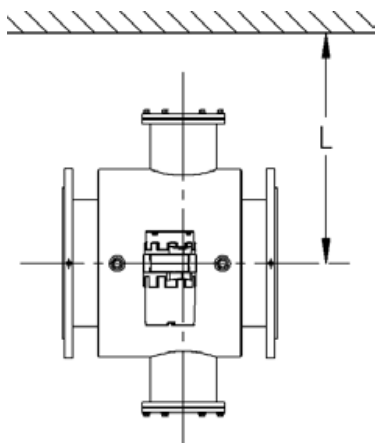
the electrodes. Below are the recommended,
and minimum, distances for centerline of the
meter to the closest wall or other obstruction.
Meter Size (in)
Distance from Centerline of meter to closest
obstruction "L"
Recommended
Minimum
6
23
17.5
8
24
18.5
10
25
19.5
12
26
20.5
14
27
21.5
16
28
22.5
18
29
23.5
20
30
24.5
24
32
26.5
30
35
29.5
36
38
32.5
42
41
35.5
48
44
38.5
54
47
41.5
Features
Sparling's Hot-Tap electrode design has several key
features:
1)
There is no interruption of flow or
depressurization of the line required
during electrode replacement or
maintenance.
2)
Sizes available from 6" - 54"
3)
Liners: Hard Rubber, Polyurethane,
Ceramic, FEP/PTFE and Polyurethane liner
for potable water certified to NSF61.
4)
No special tools required - removal can be
easily performed with standard tools.
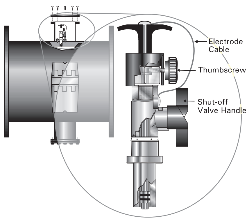
Removal/Insertion of Electrodes
Removing Hot-Tap electrodes takes only a few
straightforward steps:
1)
Remove port cover by removing 6 bolts.
2)
Remove the electrode cable from the top of
the handle by removing the screw.
3)
Loosen the thumbscrew which releases the
electrode assembly and allows the black
electrode handle to be pullled out
approximately 4" to its "STOP" position.
4)
Turn the shut-off valve handle clockwise to
close the ball valve and isolate the electrode
from the process fluid.
5)
Remove the electrode assembly with a
crescent wrench.
To insert, follow the steps in reverse.
®
Propeller Meters
®
INSTRUMENTS, LLC.
Sparling propeller meters have been developed for “clean”
water applications where the temperature of the water does
not exceed 100° F and suspended solids do not exceed 0.5% of
volume.
®
Technical Specifications
FM132
®
INSTRUMENTS, LLC.
Product Data Sheet
PDS-132
2026-07-31
VertiFlo
Vertical Propeller Flow Meter
Description
VertiFlo meters provide an economical meter
installation for accurately measuring flows from
wells equipped with submersible pumps.
Equally ideal applications are installations on
the suction side of centrifugal pumps or similar
installations where space limitations and piping
configurations deem it inadvisable to utilize the
Sparling tube-type or conventional saddle type
meters. Special requirements for meter
installation are reduced to a minimum because
the meter is installed in a standard flanged tee.
Certified Accuracy
Accuracy is within 2% of actual flow for the
specified meter range. This accuracy is
guaranteed by certified wet calibration at three
test points in Sparling's NIST traceable primary
flow laboratory. Each meter is tested at low
flow, mid-range, and high flow. A test
certificate is provided with each meter.
Principle of Operation
Sparling propeller meters utilize the simple
principle of the screw propeller to register the
total flow, much as an odometer registers auto
mileage. The rotation of the propeller affords a
basis for indicating and recording gallons per
minute or other rates.
Options
High Velocity Flows
- For applications where
continuous flow rates are above the mid-point
standard flow range ratings, high velocity
construction of the meters is recommended.
Transmitters
- Electronic transmitters are
available for installation on these meters.
See
PDS-190.
High Velocity Flows
- For applications where
continuous flow rates are above the mid-point
standard flow range ratings, high velocity
construction of the meters is recommended.
Transmitters
- Electronic transmitters are
available for installation on these meters.
See
PDS-190.
Installation
Verti-flo meterheads are drilled in accordance
with standard 125# or 250# cast iron flanged
tee requirements, as specified on customer
order, and are simply bolted into position. The
length of the meter drop pipe is manufactured
in accordance with overall dimensions as stated
in the customer's order.
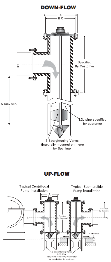
For down-flow installations, the straightening
vanes are supplied integral with the meter and
no further work is required.
For up-flow, three straightening vanes are
recommended to be welded upstream of the
meter.
Welding vanes, bolting type vanes and
stainless-steel liner and vane assemblies are
available at extra cost.
Materials
All materials used in manufacturing are highly
resistant to normal water corrosion and
recommended for water works application.
Special materials are utilized for highly
corrosive conditions. Liquid temperatures
should not exceed 100°F.
Total Flow
The cumulative total flow is shown on a six digit
straight reading totalizer in any standard
volumetric units.
®
INSTRUMENTS, LLC.
Flow Rates & Dimensions
Size
4"
6"
8"
10"
12"
14"
Standard Flow
Min
60
100
120
160
200
260
Max
400
900
1200
1600
2200
3000
High Flow
Min
120
200
240
320
400
520
Max
600
1600
2300
3000
4000
5000
150 psi
A
9
11
13.5
16
19
21
BC
7
1
2
9
1
2
11
3
4
14
1
4
17
18
3
4
# of Bolts
8
8
8
12
12
12
Size of Bolts
5
8
3
4
3
4
7
8
7
8
1
300 psi
A
10
12.5
15
17.5
20.5
23
BC
7
7
8
10
5
8
13
15
1
4
17
3
4
20
1
4
# of Bolts
8
12
12
16
16
20
Size of Bolts
1
2
3
4
7
8
1
1
1
8
1
1
2
Ordering Information
Size (in)
Flow Range (GPM)
Drop Pipe Length (in)
Standard
Up-Flow
Down-Flow
4.00
60.0 - 400
18.0
28.5
6.00
100 - 900
21.0
41.0
8.00
120 - 1200
23.0
53.0
10.0
160 - 1600
27.0
66.0
12.0
200 - 2200
29.0
78.0
14.0
260 - 3000
34.0
91.0
How to order an FM132
Table 1: BaseModelNumber
FM132
-
Direct Drive Verti-flo Meterheads
Table 2: Size
04
-
4"
06
-
6"
08
-
8"
10
-
10"
12
-
12"
14
-
14"
Table 3: HeadConnections
1
-
125# AWWA Flange (150 psi )
2
-
250# AWWA Flange (300 psi )
Table 4: FlowRange
1
-
Standard Range
2
-
High Range
Table 5: Readouts
0
-
None
Table 6: Accessories
0
-
None
1
-
Welding Vanes
2
-
Bolting Vanes
5
-
Add. Drop Pipe Length
6
-
One and Five Above
7
-
Two and Five Above
Model
Size
Head
Flow
Read
Access.
FM132
04
1
1
0
0
®
Technical Specifications
FM134
®
INSTRUMENTS, LLC.
Product Data Sheet
PDS-134
2026-07-31
VertiFlo
Vertical Propeller Flow Meter
Description
VertiFlo meters provide an economical meter
installation for accurately measuring flows from
wells equipped with submersible pumps.
Equally ideal applications are installations on
the suction side of centrifugal pumps or similar
installations where space limitations and piping
configurations deem it inadvisable to utilize the
Sparling tube-type or conventional saddle type
meters. Special requirements for meter
installation are reduced to a minimum because
the meter is installed in a standard flanged tee.
Certified Accuracy
Accuracy is within 2% of actual flow for the
specified meter range. This accuracy is
guaranteed by certified wet calibration at three
test points in Sparling's NIST traceable primary
flow laboratory. Each meter is tested at low
flow, mid-range, and high flow. A test
certificate is provided with each meter.
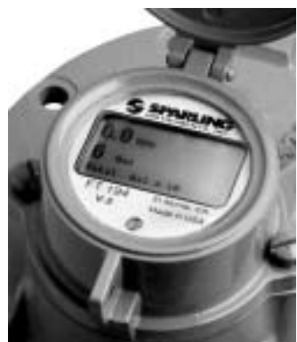
Electronic Design
The Model FM134 features the FT194-II battery
powered electronic rate/totalizer which senses
the rotation of the propeller by means of a
magnetic pickup sensor located in the gearbox.
The rate/totalizer and pickup are completely
isolated from the flow stream.
Fewer moving parts combined with a proven
Sparling design relluts in less wear, reduced
maintenace costs and longer life.
Rate Indication and Totalizer
The rate is shown on a 5-digit LCD readout and
the cumulative total flow is shown on a 8-digit
LCD straight reading totalizer in any standard
volumetric units.
The FT194 is ordered separately, it can be
mounted integrally, remotely and with the
outputs: 4-20mA and Pulse Output.
High Velocity Flows
- For applications where
continuous flow rates are above the mid-point
standard flow range ratings, high velocity
construction of the meters is recommended.
Installation
Verti-flo meterheads are drilled in accordance
with standard 125# or 250# cast iron flanged
tee requirements, as specified on customer
order, and are simply bolted into position. The
length of the meter drop pipe is manufactured
in accordance with overall dimensions as stated
in the customer's order.
For down-flow installations, the straightening
vanes are supplied integral with the meter and
no further work is required.
For up-flow, three straightening vanes are
recommended to be welded upstream of the
meter.
Welding vanes, bolting type vanes and
stainless-steel liner and vane assemblies are
available at extra cost.
Materials
All materials used in manufacturing are highly
resistant to normal water corrosion and
recommended for water works application.
Special materials are utilized for highly
corrosive conditions. Liquid temperatures
should not exceed 100°F.
®
INSTRUMENTS, LLC.
Flow Rates & Dimensions
Size
4"
6"
8"
10"
12"
14"
Low Flow
Min
50
90
100
125
150
250
Max
400
900
1200
1600
2200
3000
Standard Flow
Min
120
200
240
320
400
520
Max
600
1600
2300
3000
4000
5000
150 psi
A
9
11
13.5
16
19
21
BC
7
1
2
9
1
2
11
3
4
14
1
4
17
18
3
4
# of Bolts
8
8
8
12
12
12
Size of Bolts
5
8
3
4
3
4
7
8
7
8
1
300 psi
A
10
12.5
15
17.5
20.5
23
BC
7
7
8
10
5
8
13
15
1
4
17
3
4
20
1
4
# of Bolts
8
12
12
16
16
20
Size of Bolts
1
2
3
4
7
8
1
1
1
8
1
1
2
Ordering Information
Size (in)
Flow Range (GPM)
Drop Pipe Length (in)
Low
Up-Flow
Down-Flow
4.00
50.0 - 400
18.0
28.5
6.00
90.0 - 900
21.0
41.0
8.00
100 - 1200
23.0
53.0
10.0
125 - 1600
27.0
66.0
12.0
150 - 2200
29.0
78.0
14.0
250 - 3000
34.0
91.0
How to order an FM134
Table 1: BaseModelNumber
FM134
-
Electronic Vertiflo Meterheads
Table 2: Size
04
-
4"
06
-
6"
08
-
8"
10
-
10"
12
-
12"
14
-
14"
Table 3: HeadConnections
1
-
125# AWWA Flange (150 psi )
2
-
250# AWWA Flange (300 psi )
Table 4: Construction
4
-
Up-Flow (Vanes Not Included)
5
-
Down-Flow (Vanes Included)
Table 5: FlowRange
1
-
Low Range
2
-
Standard Range
Table 6: Readouts
0
-
None
Table 7: Accessories
0
-
None
1
-
Welding Vanes
2
-
Bolting Vanes
5
-
Add. Drop Pipe Length
6
-
One and Five Above
7
-
Two and Five Above
Model
Size
Head
Const
Flow
Read
Access.
FM134
04
1
4
1
0
0
®
Technical Specifications
FM102
®
INSTRUMENTS, LLC.
Product Data Sheet
PDS-102
2026-07-31
Series 102 Direct Drive
Meters
Description
The Series 102 Direct Drive Meters are
designed to provide accurate and reliable flow
measurements where mainline service is
required in the municipal and industrial areas.
These meters have been used for over seventy
years and have proven their reputation for
rugged, continuous duty with minimum
maintenance.
This meter can be easily maintained or repaired
with standard tools. The mechanical worm and
gear drive is positive and prevents the
possibility of slippage and low readings.
The meter is available as a meterhead only or a
meterhead complete with saddle or tube.
See
PDS-110.
Temperature Limits
Liquid working temperatures should not exceed
100°F. Propellers may be stored in air
temperatures up to 175°F.
Principle of Operation
Sparling propeller meters utilize the simple
principle of the screw propeller to register the
total flow, much as an odometer registers auto
mileage. The rotation of the propeller affords a
basis for indicating and recording gallons per
minute or other rates.
Installation
Meters must be installed in full flowing suction
or discharge lines. Avoid valves, fittings or
obstructions immediately upstream of the
meter which may cause jetting or
non-symmetrical flow profiles. It is
recommended that a minimum of five straight
pipe diameters be maintained upstream and
one diameter downstream of the flow meter.
Certified Accuracy
Accuracy is within 2% of actual flow for the
specified meter range. This accuracy is
guaranteed by certified wet calibration at three
test points in Sparling's NIST traceable primary
flow laboratory. Each meter is tested at low
flow, mid-range, and high flow. A test
certificate is provided with each meter.
Flow Ranges
These meters measure accurately over a wide
flow range of 10:1 or greater. The maximum
flow ranges can be safely exceeded by 50%
when used intermittently. Flow rates are
provided in the table under specifications for
each of the sizes.
Anticipated flow ranges and minimum and
normal flow rates should always be specified
on application sheets accompanying your
order.
®
INSTRUMENTS, LLC.
Options
High Velocity Flows
- If the minimum actual flow rate exceeds
the minimum published flow rate in Table 1, high velocity
construction is required. Specially configured propellers and
bearings are used.
When continuous flow rates exceed twice the minimum
standard flow rate in Table 1, high velocity construction is
required.
Anticipated flow ranges and minimum and normal flow rates
should always be specified on application sheets accompanying
your order. This information is required for proper evaluation of
meter construction.
Transmitters
- Electronic transmitters are available for
installation on these meters.
See PDS-190.
Rate-of-Flow Indicators
- When continuous rate of flow
indication is required, an optional rate-of-flow indicator and
totalizer is available.
See PDS-190.
Size
Flow Range (GPM)
Standard
High
2
30 - 80
60 - 150
3
35 - 200
70 - 360
4
60 - 400
120 - 600
6
100 - 900
200 - 1600
8
120 - 1200
240 - 2300
10
160 - 1600
320 - 3000
12
200 - 2200
400 - 4000
14
260 - 3000
520 - 5000
Table 1: BaseModelNumber
FM102
-
Direct Drive Meterhead
FM182
-
Basic Magnetic Drive Meterhead
FM182
-
Basic Direct Drive Meterhead
Table 2: Size
02
-
2"
03
-
3"
04
-
4"
06
-
6"
08
-
8"
10
-
10"
12
-
12"
14
-
14"
Table 3: PressureRating
1
-
150 psi
2
-
250 psi
Table 4: FlowRange
1
-
Standard Range
2
-
High Range
Table 5: Readouts
0
-
None
Table 6: Accessories
0
-
None
Model
Size
Pressure
Flow
Readouts
Access.
FM102
02
1
1
0
0
*
If meter is operated continuously at flows above the mid-point of the standard flow range, rubber bearings are required.
®
INSTRUMENTS, LLC.
Flow Rates & Dimensions
Six-bladed
propeller
Three-bladed propeller
Size (in)
2
3
4
6
8
10
12
14
Weight* (lbs)
20
20
20
25
29
34
36
37
A
8.13
8.25
9.5
10.38
11
11
11
11
B
5.13
6.25
6.75
7.31
10.63
10.63
10.63
10.63
C
3.13
3.18
4.13
3.96
5.81
5.81
5.81
5.81
Min. D
Sparling Standard
E
4
4
6.94
6.31
6.31
6.31
6.31
6.31
F
2.38
2.75
3.5
4.75
7
8
10
11
M
1.75
2.75
3.44
4.25
5.31
6.31
7.31
8
Size of Bolts
7
16
7
16
3
8
7
16
7
16
7
16
7
16
7
16
Length Of Bolts
1
1
1
1
1.25
1.25
1.25
1.25
Number Of Bolts
10
10
8
10
10
10
10
10
*
Weight of complete meter less straightening vanes.
*
Factory can advise Rates and Dimensions for meters up to 120" in size
®
Technical Specifications
FM182 Direct
®
INSTRUMENTS, LLC.
Product Data Sheet
PDS-FM182-
2026-07-31
Series 182 Direct Drive
Meters
Description
The Series 182 Direct Drive Meters are
designed to provide accurate and reliable flow
measurements where mainline service is
required in the municipal and industrial areas.
These meters have been used for over seventy
years and have proven their reputation for
rugged, continuous duty with minimum
maintenance.
This meter can be easily maintained or repaired
with standard tools. The mechanical worm and
gear drive is positive and prevents the
possibility of slippage and low readings.
The meter is available as a meterhead only or a
meterhead complete with saddle or tube.
See
PDS-110.
Temperature Limits
Liquid working temperatures should not exceed
100°F. Propellers may be stored in air
temperatures up to 175°F.
Principle of Operation
Sparling propeller meters utilize the simple
principle of the screw propeller to register the
total flow, much as an odometer registers auto
mileage. The rotation of the propeller affords a
basis for indicating and recording gallons per
minute or other rates.
Installation
Meters must be installed in full flowing suction
or discharge lines. Avoid valves, fittings or
obstructions immediately upstream of the
meter which may cause jetting or
non-symmetrical flow profiles. It is
recommended that a minimum of five straight
pipe diameters be maintained upstream and
one diameter downstream of the flow meter.
Certified Accuracy
Accuracy is within 2% of actual flow for the
specified meter range. This accuracy is
guaranteed by certified wet calibration at three
test points in Sparling's NIST traceable primary
flow laboratory. Each meter is tested at low
flow, mid-range, and high flow. A test
certificate is provided with each meter.
Flow Ranges
These meters measure accurately over a wide
flow range of 10:1 or greater. The maximum
flow ranges can be safely exceeded by 50%
when used intermittently. Flow rates are
provided in the table under specifications for
each of the sizes.
Anticipated flow ranges and minimum and
normal flow rates should always be specified
on application sheets accompanying your
order.
®
INSTRUMENTS, LLC.
Options
High Velocity Flows
- If the minimum actual flow rate exceeds
the minimum published flow rate in Table 1, high velocity
construction is required. Specially configured propellers and
bearings are used.
When continuous flow rates exceed twice the minimum
standard flow rate in Table 1, high velocity construction is
required.
Anticipated flow ranges and minimum and normal flow rates
should always be specified on application sheets accompanying
your order. This information is required for proper evaluation of
meter construction.
Transmitters
- Electronic transmitters are available for
installation on these meters.
See PDS-190.
Rate-of-Flow Indicators
- When continuous rate of flow
indication is required, an optional rate-of-flow indicator and
totalizer is available.
See PDS-190.
The meter cover plate has the same drilling as a standard 150#
Class D flange. This size is indicated by dimension "A".
Rolled steel welding-type saddles are furnished to conform to
the O.D. pipe diameter specified by the customer. "M" Drop Pipe
can be lengthened for use in concrete pipe or for special
application.
Meters are calibrated to the I.D. pipe diameter specified by
customer. Straightening vanes should be installed immediately
upstream from the propeller to insure straight flow for accurate
metering.
Size
Flow Range (GPM)
Standard
High
16
350 - 3800
700 - 6800
18
450 - 4500
900 - 8100
20
550 - 5500
1100 - 9900
24
1200 - 8000
2400 - 15300
30
1500 - 1200
3000 - 21600
36
1500 - 16000
3000 - 28800
42
2100 - 22000
4200 - 40000
48
2700 - 28000
5400 - 50000
54
3400 - 35000
6800 - 63000
60
4200 - 42000
8400 - 76000
66
5000 - 50000
10000 - 90000
72
6000 - 60000
12000 - 110000
Table 1: BaseModelNumber
FM182
-
Basic Direct Drive Meterhead
Table 2: Size
16
-
16"
18
-
18"
20
-
20"
24
-
24"
30
-
30"
36
-
36"
42
-
42"
48
-
48"
54
-
54"
60
-
60"
66
-
66"
72
-
72"
Table 3: PressureRating
1
-
150 psi
2
-
250 psi
Table 4: MDimension
1
-
Standard
6
-
Special
Table 5: FlowRange
1
-
Standard Range
2
-
High Range
Table 6: Readouts
0
-
None
Table 7: Accessories
0
-
None
1
-
Register Extension
Model
Size
Pressure
M Dim
Flow
Readouts
Access.
FM182
16
1
1
1
0
0
*
If meter is operated continuously at flows above the mid-point of the standard flow range, rubber bearings are required.
®
INSTRUMENTS, LLC.
Flow Rates & Dimensions
Size (in)
16
18
20
24
30
36
42
48
54
60
66
72
A
16
16
16
16
16
24
24
30
30
30
30
30
B
25.5
25.5
25.5
25.5
25.5
36
36
43
43
43
43
43
C
14
16
16
16
16
25.5
25.5
38.38
38.38
38.38
38.38
38.38
Min. D
4.5
4.5
4.25
4.5
4.5
6
6
6.5
6.5
6.5
6.5
6.5
F
16
18
20
24
30
36
42
48
54
60
66
72
G
4.56
4.56
4.56
4.56
4.56
6.81
6.81
9.81
9.81
9.81
9.81
9.81
H
4.25
4.25
4.25
4.25
4.25
6.5
6.5
9.5
9.5
9.5
9.5
9.5
M
12.25
13.5
14.5
16.5
19.5
24
27
30.5
33.5
36.5
39.5
42.5
N
4.13
4.13
4.13
4.13
4.13
4.63
4.63
5.5
5.5
5.5
5.5
5.5
S
*
26
26
26
26
36.5
36.5
46.75
46.75
46.75
46.75
46.75
T
12
12
12
12
12
18.75
18.75
20
20
20
20
20
Bolt Circle
22.5
22.5
22.5
22.5
22.5
32
32
39.25
39.25
39.25
39.25
39.25
Size of Bolts
1
1
4
1
1
4
1
1
4
1
1
4
1
1
4
1
1
2
1
1
2
1
1
4
1
1
4
1
1
4
1
1
4
1
1
4
Number Of Bolts
20
20
20
20
20
24
24
28
28
28
28
28
*
Weight of complete meter less straightening vanes.
*
Factory can advise Rates and Dimensions for meters up to 120" in size
®
Technical Specifications
FM182 Magnetic
®
INSTRUMENTS, LLC.
Product Data Sheet
PDS-FM182-1
2026-07-31
Series 182 Direct Drive
Meters
Description
The Series 182 Direct Drive Meters are
designed to provide accurate and reliable flow
measurements where mainline service is
required in the municipal and industrial areas.
These meters have been used for over seventy
years and have proven their reputation for
rugged, continuous duty with minimum
maintenance.
This meter can be easily maintained or repaired
with standard tools. The mechanical worm and
gear drive is positive and prevents the
possibility of slippage and low readings.
The meter is available as a meterhead only or a
meterhead complete with saddle or tube.
See
PDS-110.
Temperature Limits
Liquid working temperatures should not exceed
100°F. Propellers may be stored in air
temperatures up to 175°F.
Principle of Operation
Sparling propeller meters utilize the simple
principle of the screw propeller to register the
total flow, much as an odometer registers auto
mileage. The rotation of the propeller affords a
basis for indicating and recording gallons per
minute or other rates.
Installation
Meters must be installed in full flowing suction
or discharge lines. Avoid valves, fittings or
obstructions immediately upstream of the
meter which may cause jetting or
non-symmetrical flow profiles. It is
recommended that a minimum of five straight
pipe diameters be maintained upstream and
one diameter downstream of the flow meter.
Certified Accuracy
Accuracy is within 2% of actual flow for the
specified meter range. This accuracy is
guaranteed by certified wet calibration at three
test points in Sparling's NIST traceable primary
flow laboratory. Each meter is tested at low
flow, mid-range, and high flow. A test
certificate is provided with each meter.
Flow Ranges
These meters measure accurately over a wide
flow range of 10:1 or greater. The maximum
flow ranges can be safely exceeded by 50%
when used intermittently. Flow rates are
provided in the table under specifications for
each of the sizes.
Anticipated flow ranges and minimum and
normal flow rates should always be specified
on application sheets accompanying your
order.
®
INSTRUMENTS, LLC.
Options
High Velocity Flows
- If the minimum actual flow rate exceeds the
minimum published flow rate in Table 1, high velocity construction is
required. Specially configured propellers and bearings are used.
When continuous flow rates exceed twice the minimum standard flow
rate in Table 1, high velocity construction is required.
Anticipated flow ranges and minimum and normal flow rates should
always be specified on application sheets accompanying your order.
This information is required for proper evaluation of meter
construction.
Transmitters
- Electronic transmitters are available for installation on
these meters.
See PDS-190.
Rate-of-Flow Indicators
- When continuous rate of flow indication is
required, an optional rate-of-flow indicator and totalizer is available.
See PDS-190.
Forward-Reverse Flows
- Special tubes are available for forward-reverse
flows. These tubes contain straightening vanes both upstream and
downstream from the meter propeller. A forward-reverse totalizer is
used in place of the standard register to totalize flows in both
directions.
See PDS-190.
The meter cover plate has the same drilling as a standard 150# Class D
flange. This size is indicated by dimension "A".
Rolled steel welding-type saddles are furnished to conform to the O.D.
pipe diameter specified by the customer. "M" Drop Pipe can be
lengthened for use in concrete pipe or for special application.
Meters are calibrated to the I.D. pipe diameter specified by customer.
Straightening vanes should be installed immediately upstream from the
propeller to insure straight flow for accurate metering.
Size
Flow Range (GPM)
Standard
High
16
350 - 3800
700 - 6800
18
450 - 4500
900 - 8100
20
550 - 5500
1100 - 9900
24
1200 - 8000
2400 - 15300
30
1500 - 1200
3000 - 21600
36
1500 - 16000
3000 - 28800
42
2100 - 22000
4200 - 40000
48
2700 - 28000
5400 - 50000
54
3400 - 35000
6800 - 63000
60
4200 - 42000
8400 - 76000
66
5000 - 50000
10000 - 90000
72
6000 - 60000
12000 - 110000
Table 1: BaseModelNumber
FM182
-
Basic Magnetic Drive Meterhead
Table 2: Size
16
-
16"
18
-
18"
20
-
20"
24
-
24"
30
-
30"
36
-
36"
42
-
42"
48
-
48"
54
-
54"
60
-
60"
66
-
66"
72
-
72"
Table 3: PressureRating
1
-
150 psi
2
-
250 psi
Table 4: MDimension
1
-
Standard
6
-
Special
Table 5: FlowRange
1
-
Standard Range
2
-
High Range
Table 6: Readouts
0
-
None
Table 7: Accessories
0
-
None
1
-
Register Extension
7
-
For Forward and Reverse Flow
Model
Size
Pressure
M Dim
Flow
Readouts
Access.
FM182
16
1
1
1
0
0
*
If meter is operated continuously at flows above the mid-point of the standard flow range, rubber bearings are required.
®
INSTRUMENTS, LLC.
Flow Rates & Dimensions
Size (in)
16
18
20
24
30
36
42
48
54
60
66
72
A
16
16
16
16
16
24
24
30
30
30
30
30
B
23.5
23.5
23.5
23.5
23.5
32
32
38.75
38.75
38.75
38.75
38.75
C
13
16
16
16
16
25.25
25.25
38.38
38.38
38.38
38.38
38.38
Min. D
4
4.5
4.5
4.5
4.5
5
5
5.5
5.5
5.5
5.5
5.5
F
16
18
20
24
30
36
42
48
54
60
66
72
G
4.56
4.56
4.56
4.56
4.56
6.81
6.81
9.81
9.81
9.81
9.81
9.81
H
4.25
4.25
4.25
4.25
4.25
6.5
6.5
9.5
9.5
9.5
9.5
9.5
M
12.25
13.5
14.5
16.25
19.25
23
26
29.5
32.5
35.5
38.5
41
N
2.88
2.88
2.88
2.88
2.88
3.13
3.13
3.25
3.25
3.25
3.25
3.25
S
*
26
26
26
26
36.5
36.5
46.75
46.75
46.75
46.75
46.75
T
12
12
12
12
12
18.75
18.75
20
20
20
20
20
Bolt Circle
21.25
21.25
21.25
21.25
21.25
29.5
29.5
36
36
36
36
36
Size of Bolts
1
1
1
1
1
1
1
4
1
1
4
1
1
4
1
1
4
1
1
4
1
1
4
1
1
4
Number Of Bolts
16
16
16
16
16
20
20
28
28
28
28
28
*
Weight of complete meter less straightening vanes.
*
Factory can advise Rates and Dimensions for meters up to 120" in size
®
Technical Specifications
FM142
®
INSTRUMENTS, LLC.
Product Data Sheet
PDS-142
2026-07-31
Waterworks Intake
Meter
Description
A Waterworks Intake Meter is an economical
and easily installed meter for large volume flow
measurement at the discharge end of a closed
conduit, inverted siphon, and reservoirs.
Existing structures often provide an excellent
mounting for the meter.
Certified Accuracy
Accuracy is within 2% of actual flow for the
specified meter range. This accuracy is
guaranteed by certified wet calibration at three
test points in Sparling's NIST traceable primary
flow laboratory. Each meter is tested at low
flow, mid-range, and high flow. A test
certificate is provided with each meter.
Installation
The meter propeller, fully submerged and
facing the center of the flow at the discharge
end of a pipe, closed conduit, or inverted
siphon, is suspended from a pipe column
attached to a wall or simple support structure.
Concrete pipe or a simple culvert structrue is a
satisfactory meter tube. Gate valves or other
obstructions should be at least ten pipe
diameters upstream from the meter.
Straightening vanes may be furnished as a
separate item to insure straight flow conditions
and accurate measurement.
Materials
All materials used in manufacturing are highly
resistant to normal water corrosion and
recommended for water works application.
Special materials are utilized for highly
corrosive conditions. Liquid temperatures
should not exceed 100°F.
Propeller Design Minimizes Maintenance
- The
propeller is made of a tough , durable,
abrasion-resistant material. The conical shape
and the ability of the material to flex under
stress allows the propeller to shed debris such
as clumps of algae or rags without damage.
Rugged Construction Guarantees Long Life
-
Materials of construction have been selected to
provide many years of service. Shafts and
bearings are stainless steel, bearing housings
are Brass (10" - 30") and Cast Iron (36" - 72").
Drop pipes are Brass (10" - 30") and Steel (36" -
72").
Rate Indication and Totalizer
Total flow is shown on a 6-digit Straight
Reading Clock which registers in units or
multiple units of Gallons, Cubic Feet or other
standard units.
Flow Rate is easily obtained by timing the
register clock test hand.
Flow Ranges
These meters measure accurately over a wide
flow range of 10:1 or greater. The maximum
flow ranges can be safely exceeded by 50%
when used intermittently. Flow rates are
provided in the table under specifications for
each of the sizes.
Anticipated flow ranges and minimum and
normal flow rates should always be specified
on application sheets accompanying your
order.
®
INSTRUMENTS, LLC.
Table 1: BaseModelNumber
FM142
-
Direct Drive Open Flow Meterhead
Table 2: Size
10
-
10"
12
-
12"
14
-
14"
16
-
16"
18
-
18"
20
-
20"
24
-
24"
30
-
30"
36
-
36"
42
-
42"
48
-
48"
54
-
54"
60
-
60"
66
-
66"
72
-
72"
Table 3: Mounting
6
-
Standard Wall Brackets
Table 4: Construction
1
-
Standard
Table 5: FlowRange
1
-
Standard Range
2
-
High Range
Table 6: Readouts
0
-
None
Table 7: Accessories
0
-
None
1
-
Bolting Vanes
Model
Size
Mount
Const
Flow
Read
Access.
FM142
10
6
1
1
0
0
Size
(in)
Weight
(lbs)
B
C
D
E
F
G
Flow Range (GPM)
Standard
High
10.0
90.0
9.50
2.12
3.38
16.5
8.00
4.00
160 - 1600
360 - 2900
12.0
90.0
9.50
2.12
4.00
16.5
10.0
3.00
200 - 2000
400 - 3600
14.0
90.0
9.50
2.12
4.75
28.0
11.0
2.00
260 - 2600
520 - 4700
16.0
105
12.0
2.62
5.50
28.0
13.0
5.00
300 - 3800
600 - 6800
18.0
105
12.0
2.62
6.00
30.0
16.0
3.00
400 - 4600
800 - 8300
20.0
105
12.0
2.62
7.00
33.0
16.0
2.00
550 - 5600
1100 - 10000
24.0
105
12.0
2.62
8.00
36.0
16.0
1.00
800 - 8500
1600 - 15000
30.0
115
12.0
2.62
10.0
45.0
16.0
1.00
1200 - 12000
2400 - 21000
36.0
350
18.1
4.38
12.0
54.0
25.2
*
1500 - 16000
3000 - 29000
42.0
350
18.1
4.38
14.0
60.0
25.2
*
2100 - 22000
4200 - 40000
48.0
580
20.0
4.50
16.0
72.0
38.4
*
2700 - 28000
5400 - 50000
54.0
580
20.0
4.50
18.0
80.0
38.4
*
3400 - 35000
6800 - 63000
60.0
580
20.0
4.50
20.0
90.0
38.4
*
4200 - 42000
8400 - 75000
66.0
580
20.0
4.50
22.0
96.0
38.4
*
5000 - 50000
10000 - 90000
72.0
580
20.0
4.50
24.0
108
38.4
*
6000 - 60000
12000 - 100000
®
Technical Specifications
FM144
®
INSTRUMENTS, LLC.
Product Data Sheet
PDS-144
2026-07-31
Waterworks Intake
Meter
Electronic Propeller Meter
Description
A Waterworks Intake Meter is an economical
and easily installed meter for large volume flow
measurement at the discharge end of a closed
conduit, inverted siphon, and reservoirs.
Existing structures often provide an excellent
mounting for the meter.
Electronic Design
The Model FM144 features the FT194-II battery
powered electronic rate/totalizer which senses
the rotation of the propeller by means of a
magnetic pickup sensor located in the gearbox.
The rate/totalizer and pickup are completely
isolated from the flow stream.
Fewer moving parts combined with a proven
Sparling design relluts in less wear, reduced
maintenace costs and longer life.
Certified Accuracy
Accuracy is within 2% of actual flow for the
specified meter range. This accuracy is
guaranteed by certified wet calibration at three
test points in Sparling's NIST traceable primary
flow laboratory. Each meter is tested at low
flow, mid-range, and high flow. A test
certificate is provided with each meter.
Rate Indication and Totalizer
The rate is shown on a 4-digit LCD readout and
the cumulative total flow is shown on a 8-digit
LCD straight reading totalizer in any standard
volumetric units.
The FT194 is ordered separately, it can be
mounted integrally, remotely and with the
outputs: 4-20mA and Pulse Output.
Minimum Flows
- Minimum flows are required
before accurate registration can be obtained in
standard volumetric units.
Maximum Flows
- The maximum flow ranges
can be safely exceeded by 50% when used
intermittently.
Materials
All materials used in manufacturing are highly
resistant to normal water corrosion and
recommended for water works application.
Special materials are utilized for highly
corrosive conditions. Liquid temperatures
should not exceed 100°F.
Propeller Design Minimizes Maintenance
- The
propeller is made of a tough , durable,
abrasion-resistant material. The conical shape
and the ability of the material to flex under
stress allows the propeller to shed debris such
as clumps of algae or rags without damage.
Rugged Construction Guarantees Long Life
-
Materials of construction have been selected to
provide many years of service. Shafts and
bearings are stainless steel, bearing housings
are Brass (10" - 30") and Cast Iron (36" - 72").
Drop pipes are Brass (10" - 30") and Steel (36" -
72").
Installation
The meter propeller, fully submerged and
facing the center of the flow at the discharge
end of a pipe, closed conduit, or inverted
siphon, is suspended from a pipe column
attached to a wall or simple support structure.
Concrete pipe or a simple culvert structrue is a
satisfactory meter tube. Gate valves or other
obstructions should be at least ten pipe
diameters upstream from the meter.
Straightening vanes may be furnished as a
separate item to insure straight flow conditions
and accurate measurement.
®
INSTRUMENTS, LLC.
Table 1: BaseModelNumber
FM144
-
Electronic Open Flow Meterheads
Table 2: Size
10
-
10"
12
-
12"
14
-
14"
16
-
16"
18
-
18"
20
-
20"
24
-
24"
30
-
30"
36
-
36"
42
-
42"
48
-
48"
54
-
54"
60
-
60"
66
-
66"
72
-
72"
Table 3: Mounting
6
-
Standard Wall Brackets
Table 4: Construction
1
-
Standard
Table 5: FlowRange
1
-
Standard Range
2
-
High Range
Table 6: Readouts
0
-
None
Table 7: Accessories
0
-
None
1
-
Bolting Vanes
Model
Size
Mount
Const
Flow
Read
Access.
FM144
10
6
1
1
0
0
Size (in)
Weight
(lbs)
B
C
E
G
H
Flow Range (GPM)
Low
Standard
10.0
90.0
9.50
2.12
16.5
4.00
8.0
125 - 1600
320 - 3000
12.0
90.0
9.50
2.12
16.5
3.00
10
150 - 2200
400 - 4000
14.0
90.0
9.50
2.12
28.0
2.00
11
250 - 3000
520 - 5000
16.0
105
12.0
2.62
28.0
5.00
13
350 - 3800
700 - 6800
18.0
105
12.0
2.62
30.0
3.00
16
450 - 4500
900 - 8100
20.0
105
12.0
2.62
33.0
2.00
16
550 - 5500
1100 - 9900
24.0
105
12.0
2.62
36.0
1.00
16
800 - 8500
1600 - 15000
30.0
115
12.0
2.62
45.0
1.00
16
1200 - 12000
3000 - 21600
36.0
350
18.1
4.38
54.0
4.00
25
1500 - 16000
3000 - 28800
42.0
350
18.1
4.38
60.0
4.00
25
2000 - 22000
4200 - 40000
48.0
580
20.0
4.50
72.0
4.00
38
2500 - 28000
5400 - 50000
54.0
580
20.0
4.50
80.0
4.00
38
3200 - 35000
6800 - 63000
60.0
580
20.0
4.50
90.0
4.00
38
4000 - 42000
8400 - 76000
66.0
580
20.0
4.50
96.0
4.00
38
4750 - 50000
10000 - 90000
72.0
580
20.0
4.50
108
4.00
38
5500 - 60000
12000 - 110000
®
Technical Specifications
FM312
®
INSTRUMENTS, LLC.
Product Data Sheet
PDS-312 / 314
2026-07-31
Irrigation Saddle Meter
FM312 Bolt-on Irrigation
Saddle Propeller Meter
Description
Specifically designed to provide accurate
and reliable flow measurement to the
irrigation marketplace, Sparling's saddle
flow meter is the ideal solution to
trouble-free water flow measurement in
irrigation's severe environments. The
saddle design allows the meter to be used
on existing piping, and in many cases,
these meters can replace other saddle flow
meters.
These meters feature cast saddles and gear
boxes making them robust and reliable.
The simple and rugged design ensures that
the meter can be maintained using
standard tools.
The design is based on Sparling's proven
meters that have been used in agricultural,
municipal and industrial applications for
decades. The meter is perfect for
measuring flow in sprinkler systems and
center pivot systems as well as irrigation
systems used in agriculture, golf courses
and nurseries.
Accuracy
The meter's accuracy is ±2% Full Scale of
actual flow and each meter is certified by
wet flow calibration in a NIST traceable
flow lab.
Configurations
The meter is available in two
configurations:
1)
Mechanical, featuring a reliable
worm and gear pair that prevents
slippage and error in readings.
2)
Electronic, featuring the reliability
of fewer moving parts, permanent
magnets and a digital display.
Optional outputs allow for
communication with data systems.
Options
A full line of accessories is available:
•
Dummy covers
•
Register Extensions
•
Straightening vanes
•
Meter tubes, with plain or flanged
ends
•
Outputs: Scaled Pulse Outputs and
4-20mA
®
INSTRUMENTS, LLC.
Ordering Information
Table 1: BaseModelNumber
FM312
-
Mechanical
FM314
-
Electronic
Table 2: Size
04
-
4"
06
-
6"
08
-
8"
10
-
10"
12
-
12"
14
-
14"
Table 3: Mounting
0
-
U-Bolts
Table 4: Register
1
-
Mechanical Flow Totalizer
2
-
Mechanical Flow Totalizer and Indicator
3
-
FT194-II Digital Rate/Flow Totalizer
Table 5: Velocity
1
-
Low Range
2
-
Standard Range
Table 6: Accessories
0
-
None
1
-
Bolting Vanes
Model
Size
Mounting
Register
Velocity
Access.
FM312
04
0
1
1
0
Installation
To install the meterhead, prepare a template from the dimensions below. Using the template,
scribe a line for cutting, and cut opening, removing all burrs and slag.
Size
(in)
Max.
Press.
(psi)
Weight
(lbs)
J (in)
T (in)
Kr (in)
L (in)
Flow Range (GPM)
Low
Standard
4.00
100
20.0
4.62
7.19
2.31
2.56
60.0 - 400
120 - 600
6.00
100
25.0
6.62
6.62
3.31
0.00
100 - 900
200 - 1600
8.00
100
30.0
6.25
7.75
3.12
1.50
120 - 1200
240 - 2300
10.0
100
35.0
6.75
8.00
3.38
1.25
160 - 1600
320 - 3000
12.0
100
40.0
8.00
8.00
4.00
0.00
200 - 2000
400 - 4000
14.0
50.0
50.0
6.38
14.9
*
*
260 - 2500
520 - 5000
®
Technical Specifications
MainLine
®
INSTRUMENTS, LLC.
Product Data Sheet
PDS-104 / 184 / 194-II
2026-07-31
MainLine
Electronic Propeller Meter
FT194-II
Digital Indicator
Description
The MainLine electronic propeller meter was
designed to provide accurate and reliable flow
measurement where main line service is
required in municipal and industrial areas.
The Model MainLine features the FT194-II
battery powered electronic rate/totalizer which
senses the rotation of the propeller by means
of a magnetic pickup sensor located in the
gearbox. The rate/totalizer and pickup are
completely isolated from the flow stream.
Fewer moving parts combined with a proven
Sparling design relluts in less wear, reduced
maintenace costs and longer life.
The FM104/184 Series II is available with an
optional 4-20mA output for remote
totalizations using either the Sparling Model
787, 710 or the customer's remote totalizer
with 24VDC power supply. Registration can be
changed in the field with the Sparling Model
705 programmer.
Certified Accuracy
Accuracy is within 2% of actual flow for the
specified meter range. This accuracy is
guaranteed by certified wet calibration at three
test points in Sparling's NIST traceable primary
flow laboratory. Each meter is tested at low
flow, mid-range, and high flow. A test
certificate is provided with each meter.
Principle of Operation
Sparling propeller meters utilize the simple
principle of the screw propeller to register the
total flow, much as an odometer registers auto
mileage. The rotation of the propeller affords a
basis for indicating and recording gallons per
minute or other rates.
Applications
MainLine meters are ideal for irrigation, water
well production, pumping stations and golf
course and park water management.
Features
•
Standard ±2% Accuracy
•
Sizes available from 2" - 72"
•
Environmental Rating NEMA 4X
•
Accurately measures over flow range:
10:1
•
8 digit totalizer/indicator
•
Display "sleep mode" conserves
battery life while continuously
totalizing
•
Temporary backup power with 3.6VDC
battery
•
User selectable photocell light
sensitivity from low to bright
Optional Features
•
Remote Mounted Totalizer - up to 50ft
from meterhead
•
Open collector unsealed pulse output
with 12-24VDC loop power.
•
4-20mA Output
Materials
•
Cover Plate: Cast Iron
•
Propeller: Molded Polyethylene
•
Gearbox: Brass up to 30" and Cast Iron
above 30".
•
Bearings: SST or Rubber (High Speed)
•
Coating: Epoxy based paint
®
INSTRUMENTS, LLC.
Installation
Meters must be installed in full flowing suction or discharge
lines. Avoid valves, fittings or obstructions immediately
upstream of the meter which may cause jetting or
non-symmetrical flow profiles. It is recommended that a
minimum of five straight pipe diameters be maintained
upstream and one diameter downstream of the flow meter.
Temperature Limits
Liquid working temperatures should not exceed 100°F.
Propellers may be stored in air temperatures up to 175°F.
Flow Ranges
These meters measure accurately over a wide flow range of 10:1
or greater. The maximum flow ranges can be safely exceeded by
50% when used intermittently. Flow rates are provided in the
table under specifications for each of the sizes.
Anticipated flow ranges and minimum and normal flow rates
should always be specified on application sheets accompanying
your order.
Easy To Repair
The FM104/184 is easily repaired with common hand tools. No
special tools are required.
Outputs
Optional outputs include Scaled Pulse Outputs (Open Collector)
and 4-20mA.
FT194-II Digital Rate/Flow Totalizer
The FT194-II is a digital flow rate and totalizer with an easy to
read LCD display which features simultaneous rate and totalizer
indication. The FT194-II is standard on the FM104/184 but may
also be retrofit to existing Sparling meters see Figure 4.
A non-volatile memory holds all meter parameters such as full
scale, span, calibration factors, engineering units, damping
parameters and flow totals, even in the event of a power failure.
A photoelectric cell activates the display when the cover is
opened. After a user programmed time interval the display
reverts to an energy saving "sleep mode" while continuing to
track total flow. To reactivate the display, simply close and open
the cover. The 3.6VDC lithium battery has 3 years average life. A
low battery indication will display before battery requires
replacement. Low battery display will not affect totalization
accuracy.
Remote Mounted Transmitter
For remote indication of rate and total the FT194-II
display/transmitter may be mounted up to 50ft from the meter
head. This is ideal for situations where it is inconvenient to have
the indicator mounted integrally to the meterhead, such as a pit
or frequently flooded area. See Figure 3
The remote totalizer is furnished ready to bolt to a wall or
customer supplied plate. Optional U-bolts can be obtained for
pipe mounting. 15ft of cable is supplied standard with the
remote unit. Additional cable may be purchased when the order
is place, up to 50ft.
The optional 4-20mA and Pulse Output require connection to a
customer supplied 24VDC power supply
®
INSTRUMENTS, LLC.
FT194-II RETROFIT AVAILABLE FOR YOUR EXISTING SPARLING
METERS
Sparling's factory technicians can upgrade your existing Sparling
propeller meters to the new FT194-II indicator/totalizer. You'll
have all the benefits of the Model 104/184 Propeller Meter: fewer
moving parts, digital readout and longer life.
Sparling factory technicians remove the vertical shaft and inspect
the propeller shaft, bearings and bushings to insure proper
operation. The magnetic sensor pickup, which is completely
potted and isolated from moisture, is then inserted into the
gearbox and the electronic indicator totalizer is mounted to the
meter body. Finally the meter is wet flow calibrated at a minimum
of three test points.
For detailed metering tube dimensions please visit our website:
www.sparlinginstruments.com
and download
PDS-110
Propeller
Meter Tubes & Saddles.
®
INSTRUMENTS, LLC.
Table 2 - Standard Registration for FT194
Nom. Size
Cubic Feet
U.S. Gallons
Imperial Gallons
Acre Feet
Cubic Meters
Liters
2.0
1.0
10.0
10.0
0.00001
0.01
10.0
3.0
1.0
10.0
10.0
0.0001
0.1
100.0
4.0
10.0
100.0
100.0
0.0001
0.1
100.0
5.0
10.0
100.0
100.0
0.0001
0.1
100.0
6.0
10.0
100.0
100.0
0.001
1.0
100.0
8.0
10.0
100.0
100.0
0.001
1.0
1000.0
10.0
100.0
100.0
100.0
0.001
1.0
1000.0
12.0
100.0
1000.0
1000.0
0.001
1.0
1000.0
14.0
100.0
1000.0
1000.0
0.001
1.0
1000.0
16.0
100.0
1000.0
1000.0
0.01
10.0
10000.0
18.0
100.0
1000.0
1000.0
0.01
10.0
10000.0
20.0
100.0
1000.0
1000.0
0.01
10.0
10000.0
24.0
100.0
1000.0
1000.0
0.01
10.0
10000.0
30.0
1000.0
10000.0
10000.0
0.01
10.0
10000.0
36.0
1000.0
10000.0
10000.0
0.01
10.0
10000.0
42.0
1000.0
10000.0
10000.0
0.01
10.0
10000.0
48.0
1000.0
10000.0
10000.0
0.1
100.0
100000.0
54.0
1000.0
10000.0
10000.0
0.1
100.0
100000.0
60.0
1000.0
10000.0
10000.0
0.1
100.0
100000.0
66.0
1000.0
10000.0
10000.0
0.1
100.0
100000.0
72.0
1000.0
10000.0
10000.0
0.1
100.0
100000.0
How to order a MainLine
Table 1: BaseModelNumber
FM104
-
MainLine Electronic Propeller Meter (2-14")
FM184
-
MainLine Electronic Propeller Meter (16-72")
Table 2: Size
02
-
2"
03
-
3"
04
-
4"
06
-
6"
08
-
8"
10
-
10"
12
-
12"
14
-
14"
16
-
16"
18
-
18"
20
-
20"
24
-
24"
30
-
30"
36
-
36"
42
-
42"
48
-
48"
54
-
54"
60
-
60"
66
-
66"
72
-
72"
Table 3: PressureRating
1
-
150 psi
2
-
250 psi
Table 4: MDimension
1
-
Standard
6
-
Special
Table 5: FlowRange
1
-
Low Range
2
-
Standard Range
Table 6: Readouts
0
-
None
Table 7: Accessories
0
-
None
1
-
Register Extension
Model
Size
Pressure
M Dim
Flow
Read
Access.
FM104
02
1
1
1
0
0
How to order an FT194-II
Table 1: BaseModelNumber
FT194-II
-
FT194-II Digital Rate/Flow Totalizer
Table 2: Outputs
0
-
Display Only, No Outputs
1
-
4-20mA and Pulse Output
Table 3: Mounting
1
-
Integral Mount
2
-
Remote Mount - Wall or Pipe Mount
3
-
Remote Mount - Forward & Reverse
Totalization
Table 4: Options
Calibrator
Programmer
Mounting Hardware (Pipe)
Model
Outputs
Mount
FT194-II
0
1
Available Accessories:
□
Model 705 Programmer
□
Model 704 Calibrator
□
Register Extension
Important: This meter requires a metering tube or saddle to complete installation.
Flow Rates & Dimensions
Size
(in)
Fabr.
Steel
Cast
Iron
A
B
C
D
E
G
H
M
N
S
Flow Range (GPM)
Size of
Bolts
# of
Bolts
150#
250#
150#
250#
Low
Standard
2.00
*
20.0
*
8.13 x 5.13
8.13 x 5.13
2.38
*
4.00
3.13
0.50
1.75
1.75
2.56
*
30.0 - 80.0
60.0 - 150
*
*
3.00
*
20.0
*
8.25 x 6.25
8.25 x 6.25
2.75
*
4.00
3.18
0.63
2.75
2.75
2.56
*
35.0 - 200
70.0 - 360
*
*
4.00
20.0
*
*
9.50 x 6.75
9.50 x 6.75
3.50
*
6.94
4.13
0.63
3.44
3.44
2.56
*
50.0 - 400
120 - 600
*
*
6.00
25.0
*
*
10.4 x 7.31
10.4 x 7.31
4.75
*
6.31
3.69
0.94
4.25
4.25
2.93
*
90.0 - 900
200 - 1600
*
*
8.00
29.0
*
*
11.0 x 10.6
11.0 x 10.6
7.00
*
6.31
5.81
-0.32
5.31
5.31
2.81
*
100 - 1200
240 - 2300
*
*
10.0
34.0
*
*
11.0 x 10.6
11.0 x 10.6
8.00
*
6.31
5.81
-0.32
6.31
6.31
2.81
*
125 - 1600
320 - 3000
*
*
12.0
36.0
*
*
11.0 x 10.6
11.0 x 10.6
10.0
*
6.31
5.81
-0.32
7.31
7.31
2.81
*
150 - 2200
400 - 4000
*
*
14.0
37.0
*
*
11.0 x 10.6
11.0 x 10.6
11.0
*
6.31
5.81
-0.32
8.00
8.00
2.81
*
250 - 3000
520 - 5000
*
*
16.0
210
*
16.0
23.5
25.5
13.0
4.00
12.0
4.56
4.2
12.2
12.2
2.88
*
350 - 3800
700 - 6800
1.00
16.0
18.0
210
*
16.0
23.5
25.5
16.0
4.50
12.0
4.56
4.2
13.2
13.5
2.88
26.0
450 - 4500
900 - 8100
1.00
16.0
20.0
215
*
16.0
23.5
25.5
16.0
4.00
12.0
4.56
4.2
14.2
14.5
2.88
26.0
550 - 5500
1100 - 9900
1.00
16.0
24.0
215
*
16.0
23.5
25.5
16.0
4.50
12.0
4.56
4.2
16.2
16.5
2.88
26.0
800 - 8500
1600 - 15000
1.00
16.0
30.0
220
*
16.0
23.5
25.5
16.0
4.50
12.0
4.56
4.2
19.2
19.5
2.88
26.0
1200 - 12000
3000 - 21600
1.00
16.0
36.0
825
*
24.0
32.0
36.0
25.2
5.00
18.8
6.81
6.5
23.0
24.0
3.13
36.5
1500 - 16000
300 - 28800
1.25
20.0
42.0
835
*
24.0
32.0
36.0
25.2
5.00
18.8
6.81
6.5
26.0
27.0
3.13
36.5
200 - 22000
4200 - 40000
1.25
20.0
48.0
1350
*
30.0
38.8
43.0
25.2
5.50
20.0
9.81
9.5
29.5
30.5
3.25
46.8
2500 - 28000
5400 - 50000
1.25
28.0
54.0
1360
*
30.0
38.8
43.0
25.2
5.50
20.0
9.81
9.5
32.5
33.5
3.25
46.8
3200 - 35000
6800 - 63000
1.25
28.0
60.0
1370
*
30.0
38.8
43.0
25.2
5.50
20.0
9.81
9.5
35.5
36.5
3.25
46.8
4000 - 42000
8400 - 76000
1.25
28.0
66.0
1380
*
30.0
38.8
43.0
25.2
5.50
20.0
9.81
9.5
38.5
39.5
3.25
46.8
4750 - 50000
10000 - 90000
1.25
28.0
72.0
1390
*
30.0
38.8
43.0
25.2
5.50
20.0
9.81
9.2
41.5
42.5
3.25
46.8
5500 - 60000
12000 - 110000
1.25
28.0
The maximum flow ranges can be safely exceeded by 50% when used intermittently. Your Sparling meter utilizes specially designed propellers and bearings matched to your
flow range to insure long life.
Anticipated flow ranges and minimum and normal flow rates should always be specified on application sheets accompanying your order.
®
Technical Specifications
FM112/114
®
INSTRUMENTS, LLC.
Product Data Sheet
PDS-112 / 114
2026-07-31
Mainline Propeller
Meters
FM112 Direct Drive and FM114
Electronic Propelller Meters
'Drop in' replacement for
Masterflo Propeller Meters
Description
The FM112 and FM114 Propeller meters
are drop-in replacements for Sparling's
Masterflo meters.
The FM112 is identical in construction to
Sparling's FM102 meters except that the
FM112 features a custom coverplate and
propeller center line dimension ('M
Dimension') to allow this unit to replace
Masterflo propeller meters without any
changes to the piping or meter tube. The
FM114 is identical in construction to
Sparling's FM182 meters except that the
FM114 features a custom coverplate and
propeller center line dimension ('M
Dimension') to allow this unit to replace
Masterflo propeller meters without any
changes to the piping or meter tube.
These meters are designed to provide
accurate and reliable flow measurements
where mainline service is required in
municipal and industrial environments.
These meters have a proven design and a
reputation for rugged, continuous, duty
with minimal required maintenance.
Sparling's propeller meters are ideally
suited for clean water applications where
the temperature of the water does not
exceed 100°F and suspended solids do not
exceed 0.5%.
Certified Accuracy
Accuracy is within 2% of actual flow for the
specified meter range. This accuracy is
guaranteed by certified wet calibration at
three test points in Sparling's NIST
traceable primary flow laboratory. Each
meter is tested at low flow, mid-range, and
high flow. A test certificate is provided with
each meter.
Installation
Meters must be installed in full flowing
suction or discharge lines. Avoid valves,
fittings or obstructions immediately
upstream of the meter which may cause
jetting or non-symmetrical flow profiles. It
is recommended that a minimum of five
straight pipe diameters be maintained
upstream and one diameter downstream
of the flow meter.
Registration of flow is shown on a register
which can be furnished in any standard
units(i.e. gallons, cubic feet, acre-feet,
ettc.). This register is a separate item. For
FM112 please specify a FT191 or FT193.
For FM114 please specify a FT194-II.
Note if a new meter tube is required,
please specify FM102 / FM182 / FM182 /
FM182 / MainLine / MainLine meters.
®
INSTRUMENTS, LLC.
How to order an FM112 or FM114
Table 1: BaseModelNumber
FM112
-
Direct Drive Propeller Meter Replacement
FM114
-
Electronic Propeller Meter Replacement
Table 2: Size
04
-
4"
06
-
6"
08
-
8"
10
-
10"
12
-
12"
14
-
14"
16
-
16"
18
-
18"
20
-
20"
24
-
24"
Table 3: PressureRating
1
-
150 psi
2
-
300 psi
Table 4: MDimension
1
-
Standard (See Table)
Table 5: FlowRange
1
-
Low Range
2
-
High Range
Table 6: Readouts
0
-
3 Blade HV (16-24")
1
-
6 Blade
2
-
3 Blade (4-14")
Table 7: Accessories
0
-
None
1
-
Register Extension
Model
Size
Pressure
M Dim
Flow
Readouts
Access.
FM112
04
1
1
1
2
0
Size (in)
Low Range (GPM)
High Range (GPM)
M Dim (in)
Min
Max
Min
Max
4
50.0
400
120
600
3
7
16
6
90.0
900
200
1600
5
8
100
1200
240
2300
5
10
125
1600
320
3000
7
11
16
12
150
2200
400
4000
7
11
16
14
250
3000
520
5000
7
7
8
16
350
3800
700
6800
11
9
16
18
450
4500
900
8100
11
9
16
20
550
5500
1100
9900
11
9
16
24
800
8500
1600
15000
13
9
16
®
Technical Specifications
Totalizers
®
INSTRUMENTS, LLC.
Product Data Sheet
PDS-190
2026-07-31
Series 190 Totalizers, Indicators and
Transmitters for Mechanical Drive Propeller
Flowmeters
FT190
FT191
FT193
Description
The Series 190, 191 and 193 are used in combination
with, and mounted on Sparling propeller flowmeters to
provide mechanical totalization (registration), mechanical
indication and a variety of pulse and/or 4-20mA outputs.
FT190 - (Formerly Model 245)
Provides mechanical
totalization (registration),
mechanical rate indication.
FT193
Provides mechanical
totalization and both a true
tow-wire 4-20mA output and
true two-wire scaled
elecronic pulse output.
FT191 - (Formerly Model 249)
Provides mechanical totalization (registration).
Table 1
Readout and Output Capabilities
Type
Mechanical
Totalization
Mechanical
Rate
Indication
Outputs
4-20mA
(Two Wire)
*
Scaled
Electronic
Pulse Rate
Weight
FT190 -
(Formerly
Model 245)
Yes
Yes
No
No
No
20lbs
FT191 -
(Formerly
Model 249)
Yes
No
No
No
No
15lbs
FT193
Yes
No
Yes
Yes
Yes
20lbs
*
Full scale flow rate for 100% signal output must occur at full
scale flow rate shown in Table 4 or greater flow rate.
®
INSTRUMENTS, LLC.
Standard Specifications
MechanicalIndicator
Scale Length
..........................................................................
6"
Accuracy
...............................................................
±5% Reading
Available Scales
......................................................
See Table 4
MechanicalTotalizer
Number of Digits
....................................................................
6
Accuracy
...............................................................
2% Full Scale
Units of Registration
..............................................
See Table 2
Test Hand
..........
One full rotation per least significant digit of
totalizer.
StandardRangeOutput
True two-wire requiring external power supply
External Power Supply
..............................................
18-30VDC
Output Load Capacity
See power supply vs. output load curve
Reverse Polarity Protection
...........................................
35VDC
Accuracy
..........................................................
±0.5% Full Scale
ScaledElecPulseRate
Two-wire isolated solid state switch (photocoupled)
External Power Supply
.....................................
10VDC - 30VDC
Pulse Amplitude
.
0VDC (off) to external supply voltage minus
3VDC (on)
Output Load
...............................................................
4 W Max
Pulse On Time
................................................................
100ms
Pulse Output Registration
Equal to mechanical totallizer least
significant digit
Accuracy
............................................................
2% actual flow
OutputConnections
...
Pigtail leads through
1
2
NPT grommeted or
potted sealed conduit connection.
Enclosures
......................................................................
NEMA 3R
ElectricalRating
...................................................
General Purpose
AmbTemp
................................................................
30°F to 130°F
ConstructionMaterial
........................
Painted Die Cast Aluminum
How to Order
Table 1: BaseModelNumber
FT190
-
Mechanical Flow Totalizer and Indicator
FT191
-
Mechanical Flow Totalizer
FT193
-
4-20mA and Pulse Output
Table 2: Outputs
000
-
None (FT190 and FT191)
111
-
4-20mA and Pulse Output (FT193)
Table 3: Mounting
2
-
For Mounting on Meterhead on Same Order
3
-
Replacement for Existing Meterheads
Model
Outputs
Mount
FT190
000
2
Ordering Information
1)
Construct model number by selecting one code for each
category.
2)
If ordered with a new meter-head, state base model
number and size of meter-head. If replacement for an
existing meterhead, state serial number of existing
meterhead.
3)
Provide the following information from Tables 2 & 3.
a.
Mechanical indicator scale and units.
b.
Mechanical totalizer registration and units.
®
INSTRUMENTS, LLC.
Table 2
Standard Registration for FT191 and FT193
Nom. Size
Cubic Feet
U.S. Gallons
Imperial Gallons
Acre Feet
Cubic Meters
Liters
2.0
1.0
10.0
10.0
0.00001
0.01
10.0
3.0
1.0
10.0
10.0
0.0001
0.1
100.0
4.0
10.0
100.0
100.0
0.0001
0.1
100.0
5.0
10.0
100.0
100.0
0.0001
0.1
100.0
6.0
10.0
100.0
100.0
0.001
1.0
100.0
8.0
10.0
100.0
100.0
0.001
1.0
1000.0
10.0
100.0
100.0
100.0
0.001
1.0
1000.0
12.0
100.0
1000.0
1000.0
0.001
1.0
1000.0
14.0
100.0
1000.0
1000.0
0.001
1.0
1000.0
16.0
100.0
1000.0
1000.0
0.01
10.0
10000.0
18.0
100.0
1000.0
1000.0
0.01
10.0
10000.0
20.0
100.0
1000.0
1000.0
0.01
10.0
10000.0
24.0
100.0
1000.0
1000.0
0.01
10.0
10000.0
30.0
1000.0
10000.0
10000.0
0.01
10.0
10000.0
36.0
1000.0
10000.0
10000.0
0.01
10.0
10000.0
42.0
1000.0
10000.0
10000.0
0.01
10.0
10000.0
48.0
1000.0
10000.0
10000.0
0.1
100.0
100000.0
54.0
1000.0
10000.0
10000.0
0.1
100.0
100000.0
60.0
1000.0
10000.0
10000.0
0.1
100.0
100000.0
66.0
1000.0
10000.0
10000.0
0.1
100.0
100000.0
72.0
1000.0
10000.0
10000.0
0.1
100.0
100000.0
Table 3
Standard Registration for FT190
2"
Full Scale Indication
Registration
100
GPM
10
GALLONS
100
IGPM
10
IMPGAL
100
GPM
10
CF
200
GPM
100
GALLONS
200
GPM
10
IMPGAL
300
GPM
10
CF
0.2
CFS
10
CF
0.5
CFS
10
CF
6.0
LPS
100
LITERS
12.5
LPS
0.1
CUMTRS
3"
Full Scale Indication
Registration
200
GPM
10
GALLONS
200
IGPM
10
IMPGAL
300
GPM
10
GALLONS
300
IGPM
10
IMPGAL
300
GPM
Unit
IMPGAL
300
GPM
10
CF
300
GPM
0.0001
AF
500
GPM
100
GALLONS
500
IGPM
100
IMPGAL
500
GPM
10
CF
500
GPM
0.001
AF
0.5
CFS
10
CF
1.0
CFS
10
CF
0.5
MGD
100
GALLONS
12.5
LPS
0.1
CUMTRS
25.0
LPS
1000
LITERS
30.0
LPS
1000
LITERS
100
M3HR
Unit
CUMTRS
4"
Full Scale Indication
Registration
750
GPM
100
GALLONS
750
GPM
1000
GALLONS
750
IGPM
1000
IMPGAL
1000
GPM
100
GALLONS
1000
GPM
1000
GALLONS
1000
IGPM
1000
IMPGAL
1000
GPM
10
CF
1000
GPM
100
CF
1000
GPM
0.001
AF
2.0
CFS
10
CF
3.0
CFS
10
CF
3.0
CFS
100
CF
3.0
CFS
0.001
AF
1.0
MGD
100
GALLONS
1.5
MGD
100
GALLONS
50.0
LPS
Unit
CUMTRS
60.0
LPS
1000
LITERS
60.0
LPS
Unit
CUMTRS
75.0
LPS
Unit
CUMTRS
6"
Full Scale Indication
Registration
1000
GPM
100
GALLONS
1000
GPM
1000
GALLONS
1000
IGPM
1000
IMPGAL
1000
GPM
10
CF
1000
GPM
100
CF
1000
GPM
0.001
AF
2.0
CFS
10
CF
3.0
CFS
10
CF
3.0
CFS
100
CF
3.0
CFS
0.001
AF
1.5
MGD
1000
GALLONS
60.0
LPS
1000
LITERS
60.0
LPS
Unit
CUMTRS
75.0
LPS
Unit
CUMTRS
1400
GPM
1000
GALLONS
1400
IGPM
1000
IMPGAL
1400
GPM
100
CF
1400
GPM
0.001
AF
1400
GPM
Unit
CUMTRS
1400
GPM
0.01
ACREIN
2.0
MGD
1000
GALLONS
1700
GPM
1000
GALLONS
1700
IGPM
1000
IMPGAL
1700
GPM
100
CF
1700
GPM
0.01
AF
4.0
CFS
100
CF
4.0
CFS
0.001
AF
5.5
CFS
0.001
AF
2.5
MGD
1000
GALLONS
100
LPS
1000
LITERS
100
LPS
Unit
CUMTRS
125
LPS
1000
LITERS
8"
Full Scale Indication
Registration
1400
GPM
1000
GALLONS
1400
IGPM
1000
IMPGAL
1400
GPM
100
CF
1400
GPM
0.001
CF
1400
GPM
Unit
CUMTRS
1400
GPM
0.01
ACREIN
3.0
CFS
10
CF
3.0
CFS
100
CF
3.0
CFS
0.001
AF
2.0
MGD
1000
GALLONS
75.0
LPS
1000
LITERS
100
LPS
Unit
CUMTRS
1700
GPM
1000
GALLONS
1700
IGPM
1000
IMPGAL
1700
GPM
100
CF
1700
GPM
0.01
AF
4.0
CFS
100
CF
4.0
CFS
0.001
AF
5.5
CFS
0.001
AF
2.5
MGD
1000
GALLONS
125
LPS
1000
LITERS
2500
GPM
1000
GALLONS
2500
IGPM
1000
IMPGAL
2500
GPM
100
CF
2500
GPM
0.01
AF
2500
GPM
0.1
ACREIN
6.0
CFS
100
CF
6.0
GPM
0.02
AF
4.0
MGD
1000
GALLONS
200
LPS
0
CUMTRS
200
LPS
0.01
MEGALTR
10"
Full Scale Indication
Registration
1700
GPM
1000
GALLONS
1700
IGPM
1000
IMPGAL
1700
GPM
100
CF
1700
GPM
0.01
AG
4.0
CFS
100
CF
4.0
CFS
0.001
AF
5.5
CFS
0.001
AF
2.5
MGD
1000
GALLONS
100
LPS
1000
LITERS
125
LPS
1000
LITERS
2500
GPM
1000
GALLONS
2500
IGPM
1000
IMPGAL
2500
GPM
100
CF
2500
GPM
0.01
AF
2500
GPM
0.1
ACREIN
6.0
CFS
100
CF
6.0
CFS
0.01
AF
4.0
MGD
1000
GALLONS
200
LPS
10
CUMTRS
200
LPS
0.01
MEGALTR
3000
GPM
1000
GALLONS
3000
IGPM
1000
IMPGAL
7.5
CFS
0.001
AF
8.0
CFS
100
CF
8.0
CFS
0.01
AF
5.0
MGD
1000
GALLONS
3500
GPM
1000
GALLONS
3500
IGPM
1000
IMPGAL
3500
GPM
100
CF
3500
GPM
1000
CF
3500
GPM
0.01
AF
12"
Full Scale Indication
Registration
2500
GPM
1000
GALLONS
2500
IGPM
1000
IMPGAL
2500
GPM
100
CF
2500
GPM
0.01
AF
2500
GPM
0.1
ACREIN
6.0
CFS
100
CF
6.0
CFS
0.01
AF
4.0
MGD
1000
GALLONS
200
LPS
10
CUMTRS
200
LPS
0.01
MEGALTR
3000
GPM
1000
GALLONS
3000
IGPM
1000
IMPGAL
7.5
CFS
0.001
AF
8.0
CFS
100
CF
8.0
CFS
0.01
AF
5.0
MGD
1000
GALLONS
3500
GPM
1000
GALLONS
3500
IGPM
1000
IMPGAL
3500
GPM
100
CF
3500
GPM
1000
CF
3500
GPM
0.01
AF
4500
GPM
1000
GALLONS
4500
IGPM
1000
IMPGAL
4500
GPM
0.01
AF
4500
GPM
100
CF
10.0
CFS
100
CF
10.0
CF
0.01
AF
7.5
MGD
1000
GALLONS
250
LPS
10000
LITERS
250
LPS
10
CUMTRS
14"
Full Scale Indication
Registration
3000
GPM
1000
GALLONS
3000
IGPM
1000
IMPGAL
7.5
CFS
0.001
AF
8.0
CFS
100
CF
8.0
CFS
0.01
AF
5.0
MGD
1000
GALLONS
200
LPS
10
CUMTRS
200
LPS
0.01
MEGALTR
3500
GPM
1000
GALLONS
3500
IGPM
1000
IMPGAL
3500
GPM
100
CF
3500
GPM
0.01
AF
4500
GPM
1000
GALLONS
4500
IGPM
1000
IMPGAL
4500
GPM
0.01
AF
4500
GPM
100
CF
10.0
CFS
100
CF
10.0
CFS
0.01
AF
7.5
MGD
1000
GALLONS
250
LPS
10000
LITERS
250
LPS
10
CUMTRS
5000
GPM
1000
GALLONS
5000
IGPM
1000
IMPGAL
5000
GPM
100
CF
14.0
CFS
100
CF
300
LPS
10
CUMTRS
16"
Full Scale Indication
Registration
4500
GPM
1000
GALLONS
4500
IGPM
1000
IMPGAL
4500
GPM
0.01
AF
10.0
CFS
100
CF
10.0
CFS
0.01
AF
7.5
MGD
1000
GALLONS
250
LPS
10000
LITERS
250
LPS
10
CUMTRS
5000
GPM
1000
GALLONS
5000
IGPM
1000
IMPGAL
5000
GPM
100
CF
14.0
CFS
100
CF
300
LPS
10
CUMTRS
6000
GPM
1000
GALLONS
6000
IGPM
10
IMPGAL
6000
GPM
10000
GALLONS
6000
GPM
100
CF
7500
GPM
10000
GALLONS
15.0
CFS
100
CF
15.0
CFS
0.01
AF
10.0
MGD
1000
GALLONS
10.0
MGD
10000
GALLONS
350
LPS
10
CUMTRS
400
LPS
10
KLTRS
18"
Full Scale Indication
Registration
5000
GPM
1000
GALLONS
5000
IGPM
1000
IMPGAL
5000
GPM
100
CF
6000
GPM
100
CF
14.0
CFS
1000
CF
7.5
MGD
1000
GALLONS
300
KOS
19
CUMTRS
10000
GPM
10000
GALLONS
10000
IGPM
10000
IMPGAL
10000
GPM
0.01
AF
10000
GPM
100
CF
18.0
CFS
100
CF
18.0
CFS
1000
CF
18.0
CFS
0.01
AF
20.0
CFS
1000
CF
20.0
CFS
0.01
AF
25.0
CFS
1000
CF
25.0
CFS
0.01
AF
15.0
MGD
1000
GALLONS
15.0
MGD
10000
GALLONS
750
LPS
10
CUMTRS
20"
Full Scale Indication
Registration
6000
GPM
1000
GALLONS
6000
IGPM
1000
IMPGAL
6000
GPM
10000
GALLONS
7500
GPM
10000
GALLONS
10000
GPM
10000
GALLONS
10000
IGPM
10000
GALLONS
10000
GPM
0.01
AF
10000
GPM
100
CF
15.0
CFS
100
CF
15.0
CFS
0.01
AF
18.0
CFS
100
CF
18.0
CFS
1000
CF
18.0
CFS
0.01
AF
20.0
CFS
1000
CF
20.0
CFS
0.01
AF
25.0
CFS
1000
CF
25.0
CFS
0.01
AF
10.0
MGD
1000
GALLONS
10.0
MGD
10000
GALLONS
10.0
MGD
10000
GALLONS
15.0
MGD
1000
GALLONS
15.0
MGD
10000
GALLONS
350
LPS
10
CUMTRS
400
LPS
10
KLTRS
750
LPS
10
CUMTRS
24"
Full Scale Indication
Registration
10000
GPM
10000
GALLONS
10000
IGPM
10000
IMPGAL
10000
GPM
0.01
AF
10000
GPM
100
CF
15000
GPM
10000
GALLONS
15000
IGPM
10000
IMPGAL
17000
GPM
10000
GALLONS
17000
IGPM
10000
IMPGAL
18.0
CFS
100
CF
18.0
CFS
1000
CF
18.0
CFS
0.01
AF
20.0
CFS
1000
CF
20.0
CFS
0.01
AF
25.0
CFS
1000
CF
25.0
CFS
0.01
AF
30.0
CFS
1000
CF
34.0
CFS
0.01
AF
15.0
MGD
1000
GALLONS
15.0
MGD
10000
GALLONS
20.0
MGD
10000
GALLONS
30.0
MGD
10000
GALLONS
750
LPS
10
CUMTRS
1000
LPS
100
CUMTRS
1500
LPS
100
KLTRS
30"
Full Scale Indication
Registration
15000
GPM
10000
GALLONS
15000
IGPM
10000
IMPGAL
17000
GPM
10000
GALLONS
17000
IGPM
10000
IMPGAL
25000
GPM
10000
GALLONS
15000
IGPM
10000
IMPGAL
30.0
CFS
1000
CF
34.0
CFS
0.01
AF
50.0
CFS
1000
CF
50.0
CFS
0.01
AF
20.0
MGD
10000
GALLONS
30.0
MGD
10000
GALLONS
40.0
MGD
10000
GALLONS
1000
LPS
100
CUMTRS
1500
LPS
100
KLTRS
2000
LPS
100
CUMTRS
36"
Full Scale Indication
Registration
17000
GPM
10000
GALLONS
17000
IGPM
10000
IMPGAL
25000
GPM
10000
GALLONS
25000
IGPM
10000
IMPGAL
35000
GPM
10000
GALLONS
35000
IGPM
10000
IMPGAL
50.0
CFS
1000
CF
50.0
CFS
0.01
AF
75.0
CFS
0.01
AF
30.0
MGD
10000
GALLONS
40.0
MGD
10000
GALLONS
60.0
MGD
10000
GALLONS
1500
LPS
100
KLTRS
2000
LPS
100
CUMTRS
42"
Full Scale Indication
Registration
25000
GPM
10000
GALLONS
25000
IGPM
10000
IMPGAL
35000
GPM
10000
GALLONS
35000
IGPM
10000
IMPGAL
45000
GPM
10000
GALLONS
45000
IGPM
10000
IMPGAL
50.0
CFS
1000
CF
50.0
CFS
0.01
AF
75.0
CFS
0.1
AF
100
CFS
1000
CF
40.0
MGD
10000
GALLONS
60.0
MGD
10000
GALLONS
75.0
MGD
10000
GALLONS
2000
LPS
100
CUMTRS
5000
LPS
100
CUMTRS
48"
Full Scale Indication
Registration
35000
GPM
10000
GALLONS
35000
IGPM
10000
IMPGAL
45000
GPM
10000
GALLONS
45000
IGPM
10000
GALLONS
75.0
CFS
0.1
AF
100
CFS
1000
CF
60.0
MGD
10000
GALLONS
75.0
MGD
10000
GALLONS
2000
LPS
100
CUMTRS
5000
LPS
100
CUMTRS
54"
Full Scale Indication
Registration
40000
GPM
10000
GALLONS
40000
IGPM
10000
IMPGAL
75.0
CFS
1000
CF
75.0
CFS
0.1
AF
75.0
MGD
10000
GALLONS
3000
LPS
100
CUMTRS
60"
Full Scale Indication
Registration
45000
GPM
10000
GALLONS
45000
IGPM
10000
IMPGAL
60000
GPM
10000
GALLONS
60000
IGPM
10000
IMPGAL
75000
GPM
10000
GALLONS
75000
IGPM
10000
IMPGAL
100
CFS
10000
CF
150
CFS
10000
CF
150
CFS
0.01
AF
75.0
MGD
10000
GALLONS
100
MGD
10000
GALLONS
5000
LPS
100
CUMTRS
66" and72"
Full Scale Indication
Registration
60000
GPM
10000
GALLONS
60000
IGPM
10000
IMPGAL
75000
GPM
10000
GALLONS
75000
IGPM
10000
IMPGAL
®
Technical Specifications
FT190-111
®
INSTRUMENTS, LLC.
Product Data Sheet
PDS-190-111
2026-07-31
Series 190 Totalizers, Indicators and
Transmitters for Mechanical Drive Propeller
Flowmeters
FT190-111
Description
For applications where the environment is unfriendly to a digital microprocessor device, Sparling has updated its FT190
to incorporate a 4-20mA and scaled pulse output. The FT190 is a rugged mechanical transmitter that has been
successfully used in the field for over thirty years and the FT1990-111 continues Sparling's tradition of highly robust
solutions for the flow metering world.
The FT190-111 mechanical indicator/totalizer is used in combination with, and mounted on Sparling mechanical
propeller flowmeters to provide mechanical totalization (registration), mechanical indication (flow rate) and a 4-20mA
and scaled pulse output.
Readout and Output Capabilities
Type
Mechanical
Totalization
Mechanical
Rate
Indication
Outputs
4-20mA
(Two Wire)
*
Scaled
Electronic
Pulse Rate
Weight
FT190 -
(Formerly
Model 245)
Yes
Yes
No
No
No
20lbs
FT191 -
(Formerly
Model 249)
Yes
No
No
No
No
15lbs
FT193
Yes
No
Yes
Yes
Yes
20lbs
®
INSTRUMENTS, LLC.
Standard Specifications
MechanicalIndicator
Scale Length
..........................................................................
6"
Accuracy
...............................................................
±5% Reading
Available Scales
......................................................
See Table 4
MechanicalTotalizer
Number of Digits
....................................................................
6
Accuracy
...............................................................
2% Full Scale
Units of Registration
..............................................
See Table 2
Test Hand
..........
One full rotation per least significant digit of
totalizer.
StandardRangeOutput
True two-wire requiring external power supply
External Power Supply
..............................................
18-30VDC
Output Load Capacity
See power supply vs. output load curve
Reverse Polarity Protection
...........................................
35VDC
Accuracy
..........................................................
±0.5% Full Scale
ScaledElecPulseRate
Two-wire isolated solid state switch (photocoupled)
External Power Supply
.....................................
10VDC - 30VDC
Pulse Amplitude
.
0VDC (off) to external supply voltage minus
3VDC (on)
Output Load
...............................................................
4 W Max
Pulse On Time
................................................................
100ms
Pulse Output Registration
Equal to mechanical totallizer least
significant digit
Accuracy
............................................................
2% actual flow
OutputConnections
...
Pigtail leads through
1
2
NPT grommeted or
potted sealed conduit connection.
Enclosures
......................................................................
NEMA 3R
ElectricalRating
...................................................
General Purpose
AmbTemp
................................................................
30°F to 130°F
ConstructionMaterial
........................
Painted Die Cast Aluminum
How to Order
Table 1: BaseModelNumber
FT190
-
Mechanical Flow Totalizer and Indicator
FT191
-
Mechanical Flow Totalizer
FT193
-
4-20mA and Pulse Output
Table 2: Outputs
111
-
4-20mA and Pulse Output
Table 3: Mounting
2
-
For Mounting on Meterhead on Same Order
3
-
Replacement for Existing Meterheads
Model
Outputs
Mount
FT190
111
2
Ordering Information
1)
Construct model number by selecting one code for each
category.
2)
If ordered with a new meter-head, state base model
number and size of meter-head. If replacement for an
existing meterhead, state serial number of existing
meterhead.
3)
Provide the following information from Tables 2 & 3.
a.
Mechanical indicator scale and units.
b.
Mechanical totalizer registration and units.
®
INSTRUMENTS, LLC.
Standard Registration for FT190
2"
Full Scale Indication
Registration
100
GPM
10
GALLONS
100
IGPM
10
IMPGAL
100
GPM
10
CF
200
GPM
100
GALLONS
200
GPM
10
IMPGAL
300
GPM
10
CF
0.2
CFS
10
CF
0.5
CFS
10
CF
6.0
LPS
100
LITERS
12.5
LPS
0.1
CUMTRS
3"
Full Scale Indication
Registration
200
GPM
10
GALLONS
200
IGPM
10
IMPGAL
300
GPM
10
GALLONS
300
IGPM
10
IMPGAL
300
GPM
Unit
IMPGAL
300
GPM
10
CF
300
GPM
0.0001
AF
500
GPM
100
GALLONS
500
IGPM
100
IMPGAL
500
GPM
10
CF
500
GPM
0.001
AF
0.5
CFS
10
CF
1.0
CFS
10
CF
0.5
MGD
100
GALLONS
12.5
LPS
0.1
CUMTRS
25.0
LPS
1000
LITERS
30.0
LPS
1000
LITERS
100
M3HR
Unit
CUMTRS
4"
Full Scale Indication
Registration
750
GPM
100
GALLONS
750
GPM
1000
GALLONS
750
IGPM
1000
IMPGAL
1000
GPM
100
GALLONS
1000
GPM
1000
GALLONS
1000
IGPM
1000
IMPGAL
1000
GPM
10
CF
1000
GPM
100
CF
1000
GPM
0.001
AF
2.0
CFS
10
CF
3.0
CFS
10
CF
3.0
CFS
100
CF
3.0
CFS
0.001
AF
1.0
MGD
100
GALLONS
1.5
MGD
100
GALLONS
50.0
LPS
Unit
CUMTRS
60.0
LPS
1000
LITERS
60.0
LPS
Unit
CUMTRS
75.0
LPS
Unit
CUMTRS
6"
Full Scale Indication
Registration
1000
GPM
100
GALLONS
1000
GPM
1000
GALLONS
1000
IGPM
1000
IMPGAL
1000
GPM
10
CF
1000
GPM
100
CF
1000
GPM
0.001
AF
2.0
CFS
10
CF
3.0
CFS
10
CF
3.0
CFS
100
CF
3.0
CFS
0.001
AF
1.5
MGD
1000
GALLONS
60.0
LPS
1000
LITERS
60.0
LPS
Unit
CUMTRS
75.0
LPS
Unit
CUMTRS
1400
GPM
1000
GALLONS
1400
IGPM
1000
IMPGAL
1400
GPM
100
CF
1400
GPM
0.001
AF
1400
GPM
Unit
CUMTRS
1400
GPM
0.01
ACREIN
2.0
MGD
1000
GALLONS
1700
GPM
1000
GALLONS
1700
IGPM
1000
IMPGAL
1700
GPM
100
CF
1700
GPM
0.01
AF
4.0
CFS
100
CF
4.0
CFS
0.001
AF
5.5
CFS
0.001
AF
2.5
MGD
1000
GALLONS
100
LPS
1000
LITERS
100
LPS
Unit
CUMTRS
125
LPS
1000
LITERS
8"
Full Scale Indication
Registration
1400
GPM
1000
GALLONS
1400
IGPM
1000
IMPGAL
1400
GPM
100
CF
1400
GPM
0.001
CF
1400
GPM
Unit
CUMTRS
1400
GPM
0.01
ACREIN
3.0
CFS
10
CF
3.0
CFS
100
CF
3.0
CFS
0.001
AF
2.0
MGD
1000
GALLONS
75.0
LPS
1000
LITERS
100
LPS
Unit
CUMTRS
1700
GPM
1000
GALLONS
1700
IGPM
1000
IMPGAL
1700
GPM
100
CF
1700
GPM
0.01
AF
4.0
CFS
100
CF
4.0
CFS
0.001
AF
5.5
CFS
0.001
AF
2.5
MGD
1000
GALLONS
125
LPS
1000
LITERS
2500
GPM
1000
GALLONS
2500
IGPM
1000
IMPGAL
2500
GPM
100
CF
2500
GPM
0.01
AF
2500
GPM
0.1
ACREIN
6.0
CFS
100
CF
6.0
GPM
0.02
AF
4.0
MGD
1000
GALLONS
200
LPS
0
CUMTRS
200
LPS
0.01
MEGALTR
10"
Full Scale Indication
Registration
1700
GPM
1000
GALLONS
1700
IGPM
1000
IMPGAL
1700
GPM
100
CF
1700
GPM
0.01
AG
4.0
CFS
100
CF
4.0
CFS
0.001
AF
5.5
CFS
0.001
AF
2.5
MGD
1000
GALLONS
100
LPS
1000
LITERS
125
LPS
1000
LITERS
2500
GPM
1000
GALLONS
2500
IGPM
1000
IMPGAL
2500
GPM
100
CF
2500
GPM
0.01
AF
2500
GPM
0.1
ACREIN
6.0
CFS
100
CF
6.0
CFS
0.01
AF
4.0
MGD
1000
GALLONS
200
LPS
10
CUMTRS
200
LPS
0.01
MEGALTR
3000
GPM
1000
GALLONS
3000
IGPM
1000
IMPGAL
7.5
CFS
0.001
AF
8.0
CFS
100
CF
8.0
CFS
0.01
AF
5.0
MGD
1000
GALLONS
3500
GPM
1000
GALLONS
3500
IGPM
1000
IMPGAL
3500
GPM
100
CF
3500
GPM
1000
CF
3500
GPM
0.01
AF
12"
Full Scale Indication
Registration
2500
GPM
1000
GALLONS
2500
IGPM
1000
IMPGAL
2500
GPM
100
CF
2500
GPM
0.01
AF
2500
GPM
0.1
ACREIN
6.0
CFS
100
CF
6.0
CFS
0.01
AF
4.0
MGD
1000
GALLONS
200
LPS
10
CUMTRS
200
LPS
0.01
MEGALTR
3000
GPM
1000
GALLONS
3000
IGPM
1000
IMPGAL
7.5
CFS
0.001
AF
8.0
CFS
100
CF
8.0
CFS
0.01
AF
5.0
MGD
1000
GALLONS
3500
GPM
1000
GALLONS
3500
IGPM
1000
IMPGAL
3500
GPM
100
CF
3500
GPM
1000
CF
3500
GPM
0.01
AF
4500
GPM
1000
GALLONS
4500
IGPM
1000
IMPGAL
4500
GPM
0.01
AF
4500
GPM
100
CF
10.0
CFS
100
CF
10.0
CF
0.01
AF
7.5
MGD
1000
GALLONS
250
LPS
10000
LITERS
250
LPS
10
CUMTRS
14"
Full Scale Indication
Registration
3000
GPM
1000
GALLONS
3000
IGPM
1000
IMPGAL
7.5
CFS
0.001
AF
8.0
CFS
100
CF
8.0
CFS
0.01
AF
5.0
MGD
1000
GALLONS
200
LPS
10
CUMTRS
200
LPS
0.01
MEGALTR
3500
GPM
1000
GALLONS
3500
IGPM
1000
IMPGAL
3500
GPM
100
CF
3500
GPM
0.01
AF
4500
GPM
1000
GALLONS
4500
IGPM
1000
IMPGAL
4500
GPM
0.01
AF
4500
GPM
100
CF
10.0
CFS
100
CF
10.0
CFS
0.01
AF
7.5
MGD
1000
GALLONS
250
LPS
10000
LITERS
250
LPS
10
CUMTRS
5000
GPM
1000
GALLONS
5000
IGPM
1000
IMPGAL
5000
GPM
100
CF
14.0
CFS
100
CF
300
LPS
10
CUMTRS
16"
Full Scale Indication
Registration
4500
GPM
1000
GALLONS
4500
IGPM
1000
IMPGAL
4500
GPM
0.01
AF
10.0
CFS
100
CF
10.0
CFS
0.01
AF
7.5
MGD
1000
GALLONS
250
LPS
10000
LITERS
250
LPS
10
CUMTRS
5000
GPM
1000
GALLONS
5000
IGPM
1000
IMPGAL
5000
GPM
100
CF
14.0
CFS
100
CF
300
LPS
10
CUMTRS
6000
GPM
1000
GALLONS
6000
IGPM
10
IMPGAL
6000
GPM
10000
GALLONS
6000
GPM
100
CF
7500
GPM
10000
GALLONS
15.0
CFS
100
CF
15.0
CFS
0.01
AF
10.0
MGD
1000
GALLONS
10.0
MGD
10000
GALLONS
350
LPS
10
CUMTRS
400
LPS
10
KLTRS
18"
Full Scale Indication
Registration
5000
GPM
1000
GALLONS
5000
IGPM
1000
IMPGAL
5000
GPM
100
CF
6000
GPM
100
CF
14.0
CFS
1000
CF
7.5
MGD
1000
GALLONS
300
KOS
19
CUMTRS
10000
GPM
10000
GALLONS
10000
IGPM
10000
IMPGAL
10000
GPM
0.01
AF
10000
GPM
100
CF
18.0
CFS
100
CF
18.0
CFS
1000
CF
18.0
CFS
0.01
AF
20.0
CFS
1000
CF
20.0
CFS
0.01
AF
25.0
CFS
1000
CF
25.0
CFS
0.01
AF
15.0
MGD
1000
GALLONS
15.0
MGD
10000
GALLONS
750
LPS
10
CUMTRS
20"
Full Scale Indication
Registration
6000
GPM
1000
GALLONS
6000
IGPM
1000
IMPGAL
6000
GPM
10000
GALLONS
7500
GPM
10000
GALLONS
10000
GPM
10000
GALLONS
10000
IGPM
10000
GALLONS
10000
GPM
0.01
AF
10000
GPM
100
CF
15.0
CFS
100
CF
15.0
CFS
0.01
AF
18.0
CFS
100
CF
18.0
CFS
1000
CF
18.0
CFS
0.01
AF
20.0
CFS
1000
CF
20.0
CFS
0.01
AF
25.0
CFS
1000
CF
25.0
CFS
0.01
AF
10.0
MGD
1000
GALLONS
10.0
MGD
10000
GALLONS
10.0
MGD
10000
GALLONS
15.0
MGD
1000
GALLONS
15.0
MGD
10000
GALLONS
350
LPS
10
CUMTRS
400
LPS
10
KLTRS
750
LPS
10
CUMTRS
24"
Full Scale Indication
Registration
10000
GPM
10000
GALLONS
10000
IGPM
10000
IMPGAL
10000
GPM
0.01
AF
10000
GPM
100
CF
15000
GPM
10000
GALLONS
15000
IGPM
10000
IMPGAL
17000
GPM
10000
GALLONS
17000
IGPM
10000
IMPGAL
18.0
CFS
100
CF
18.0
CFS
1000
CF
18.0
CFS
0.01
AF
20.0
CFS
1000
CF
20.0
CFS
0.01
AF
25.0
CFS
1000
CF
25.0
CFS
0.01
AF
30.0
CFS
1000
CF
34.0
CFS
0.01
AF
15.0
MGD
1000
GALLONS
15.0
MGD
10000
GALLONS
20.0
MGD
10000
GALLONS
30.0
MGD
10000
GALLONS
750
LPS
10
CUMTRS
1000
LPS
100
CUMTRS
1500
LPS
100
KLTRS
30"
Full Scale Indication
Registration
15000
GPM
10000
GALLONS
15000
IGPM
10000
IMPGAL
17000
GPM
10000
GALLONS
17000
IGPM
10000
IMPGAL
25000
GPM
10000
GALLONS
15000
IGPM
10000
IMPGAL
30.0
CFS
1000
CF
34.0
CFS
0.01
AF
50.0
CFS
1000
CF
50.0
CFS
0.01
AF
20.0
MGD
10000
GALLONS
30.0
MGD
10000
GALLONS
40.0
MGD
10000
GALLONS
1000
LPS
100
CUMTRS
1500
LPS
100
KLTRS
2000
LPS
100
CUMTRS
36"
Full Scale Indication
Registration
17000
GPM
10000
GALLONS
17000
IGPM
10000
IMPGAL
25000
GPM
10000
GALLONS
25000
IGPM
10000
IMPGAL
35000
GPM
10000
GALLONS
35000
IGPM
10000
IMPGAL
50.0
CFS
1000
CF
50.0
CFS
0.01
AF
75.0
CFS
0.01
AF
30.0
MGD
10000
GALLONS
40.0
MGD
10000
GALLONS
60.0
MGD
10000
GALLONS
1500
LPS
100
KLTRS
2000
LPS
100
CUMTRS
42"
Full Scale Indication
Registration
25000
GPM
10000
GALLONS
25000
IGPM
10000
IMPGAL
35000
GPM
10000
GALLONS
35000
IGPM
10000
IMPGAL
45000
GPM
10000
GALLONS
45000
IGPM
10000
IMPGAL
50.0
CFS
1000
CF
50.0
CFS
0.01
AF
75.0
CFS
0.1
AF
100
CFS
1000
CF
40.0
MGD
10000
GALLONS
60.0
MGD
10000
GALLONS
75.0
MGD
10000
GALLONS
2000
LPS
100
CUMTRS
5000
LPS
100
CUMTRS
48"
Full Scale Indication
Registration
35000
GPM
10000
GALLONS
35000
IGPM
10000
IMPGAL
45000
GPM
10000
GALLONS
45000
IGPM
10000
GALLONS
75.0
CFS
0.1
AF
100
CFS
1000
CF
60.0
MGD
10000
GALLONS
75.0
MGD
10000
GALLONS
2000
LPS
100
CUMTRS
5000
LPS
100
CUMTRS
54"
Full Scale Indication
Registration
40000
GPM
10000
GALLONS
40000
IGPM
10000
IMPGAL
75.0
CFS
1000
CF
75.0
CFS
0.1
AF
75.0
MGD
10000
GALLONS
3000
LPS
100
CUMTRS
60"
Full Scale Indication
Registration
45000
GPM
10000
GALLONS
45000
IGPM
10000
IMPGAL
60000
GPM
10000
GALLONS
60000
IGPM
10000
IMPGAL
75000
GPM
10000
GALLONS
75000
IGPM
10000
IMPGAL
100
CFS
10000
CF
150
CFS
10000
CF
150
CFS
0.01
AF
75.0
MGD
10000
GALLONS
100
MGD
10000
GALLONS
5000
LPS
100
CUMTRS
66" and72"
Full Scale Indication
Registration
60000
GPM
10000
GALLONS
60000
IGPM
10000
IMPGAL
75000
GPM
10000
GALLONS
75000
IGPM
10000
IMPGAL
®
Technical Specifications
Register Extension
®
INSTRUMENTS, LLC.
PDS-146
2026-07-31
Register Extension
Model 146
This rigid extension is suggested for pit
or other installations to raise the
register clock to a more convenient
level for reading and servicing. The
extension is coupled directly to the
meterhead, replacing the original
register clock. Installation can normally
be completed in the field without
removing the meter from the line. The
original register clock is relocated on
top of the extension.
The original register clock is relocated
on top of the extension. To order an
extension, simply specify the distance
requested on the above drawing. Not
suitable for Masterflo Models. Consult
Factory.
®
Technical Specifications
Tubes and Saddles
®
INSTRUMENTS, LLC.
Product Data Sheet
PDS-110
2026-07-31
Propeller Meter Tubes
and Saddles
Series 100 Meters and
Accessories
Description
Sparling MainLine direct or magnetic drive propeller meters may be furnished with a
flanged tube or with a saddle for field welding onto the customer's pipe
Tubes
Small tubes up to 3" are provided in heavy duty cast iron. Larger tubes are epxoy
polyamide lined and coated fabricated steel. Meters 6" and larger are equipped with
three integrally mounted straightening vanes. Flanges are as required.
150# or 250# AWWA
Saddles
Saddles for meterheads from 6" - 14" are provided in heavy duty cast steel with the
Sparling standard bolt pattern. Saddles for meterheads from 16" - 72" are fabricated.
Construction Material
Tubes
Tube
....................................
Cast Iron (2" - 3")
Fabricated Steel (4" - 36")
Flanges
................................
150# or 250# AWWA
BoltPattern
.........................
Sparling standard bolt pattern (2" - 14")
AWWA Flange Compliant (16" - 36")
Vanes
..................................
Not Included (2" - 4")
Integrally welded in tube (6" - 36")
Saddles
Saddle
.................................
Cast Steel (6" - 14")
Fabricated Steel (16" - 72")
BoltPattern
.........................
Sparling standard bolt pattern (2" - 14")
AWWA Flange Compliant (16" - 72")
Vanes
..................................
Fabricated Carbon Steel
®
INSTRUMENTS, LLC.
Basic Welding Saddle
150 MWP Welding Saddles
Size
Weight (lbs)
A
B
D
G*
M
S
Bolt Circle
Size of Bolts
Number Of
Bolts
6
20
7.625
9.25
*
6.625
4.25
9.25
*
7
16
10
8
30
8.25
11.75
*
8.625
5.3125
11.75
*
7
16
10
10
35
8.25
11.75
*
10.75
6.3125
11.75
*
7
16
10
12
55
8.25
11.75
*
12.75
7.3125
11.75
*
7
16
10
14
70
8.25
11.75
*
14
8
11.75
*
7
16
10
16
145
16
23.5
4
16
12.25
*
21.25
1
16
18
150
16
23.5
4
18
13.5
26
21.25
1
16
20
155
16
23.5
4
20
14.5
26
21.25
1
16
24
165
16
23.5
4.5
24
16.25
26
21.25
1
16
30
185
16
23.5
4.5
30
19.25
26
21.25
1
16
36
275
24
32
5
36
23
36.5
29.5
1
1
4
20
42
295
24
32
5
42
26
36.5
29.5
1
1
4
20
48
550
30
38.75
5.5
48
49.5
46.75
36
1
1
4
28
54
560
30
38.75
5.5
54
32.5
46.75
36
1
1
4
28
60
580
30
38.75
5.5
60
35.5
46.75
36
1
1
4
28
66
600
30
38.75
5.5
66
38.5
46.75
36
1
1
4
28
72
625
30
38.75
5.5
72
41
46.75
36
1
1
4
28
250 MWP Welding Saddles
Size
Weight (lbs)
A
B
D
G*
M
S
Bolt Circle
Size of Bolts
Number Of
Bolts
6
20
7.625
9.25
*
6.625
4.25
9.25
*
7
16
10
8
30
8.25
11.75
*
8.625
5.3125
11.75
*
7
16
10
10
30
8.25
11.75
*
10.75
6.3125
11.75
*
7
16
10
12
30
8.25
11.75
*
12.75
7.3125
11.75
*
7
16
10
14
30
8.25
11.75
*
14
8
11.75
*
7
16
10
16
260
16
25.5
5
16
12.25
*
22.5
1
1
4
20
18
265
16
25.5
5
18
13.5
26
22.5
1
1
4
20
20
270
16
25.5
5
20
14.5
26
22.5
1
1
4
20
24
275
16
25.5
5
24
16.25
26
22.5
1
1
4
20
30
480
16
25.5
5
30
19.25
26
22.5
1
1
4
20
36
485
24
36
6
36
23
36.5
32
1
1
2
24
42
505
24
36
6
42
26
36.5
32
1
1
2
24
48
710
30
43
7
48
49.5
46.75
39.25
1
3
4
28
54
720
30
43
7
54
32.5
46.75
39.25
1
3
4
28
60
730
30
43
7
60
35.5
46.75
39.25
1
3
4
28
66
740
30
43
7
66
38.5
46.75
39.25
1
3
4
28
72
750
30
43
7
72
41
46.75
39.25
1
3
4
28
®
INSTRUMENTS, LLC.
Straightening vanes
Pipe Dia.
(in)
6
8
10
12
14
16
18
20
24
30
36
42
48
54
60
66
H
4
4
4
4
4
8
8
8
8
8
12
12
15
15
15
15
How to Order
Table 1: BaseModelNumber
MT1
-
Basic Meter Tube
Table 2: Size
02
-
2"
03
-
3"
04
-
4"
06
-
6"
08
-
8"
10
-
10"
12
-
12"
14
-
14"
16
-
16"
18
-
18"
20
-
20"
24
-
24"
30
-
30"
36
-
36"
Table 3: EndConnections
1
-
AWWA Cl (125#)
1
-
AWWA Cl (250#)
Table 4: FlowDirection
1
-
Forward
Table 5: Coating
1
-
Standard
Model
Size
EndConnections
FlowDirection
Coating
MT1
02
1
1
1
Table 1: BaseModelNumber
MS1
-
Basic Welding Saddle
Table 2: Size
06
-
6"
08
-
8"
10
-
10"
12
-
12"
14
-
14"
16
-
16"
18
-
18"
20
-
20"
24
-
24"
30
-
30"
36
-
36"
42
-
42"
48
-
48"
54
-
54"
60
-
60"
66
-
66"
72
-
72"
Table 3: PressureRating
1
-
150 psi
2
-
250 psi
Table 4: MDimension
0
-
Standard
Table 5: Accessories
0
-
None
1
-
Welding Vanes
2
-
Bolting Vanes
Model
Size
Pressure
M Dim
Access.
MS1
06
1
0
0
®
INSTRUMENTS, LLC.
Basic Meter Tube
150 MWP Welding Saddles
Size
Weight (lbs)
A
B
C
D
E
F
M
Size of
Bolts
Number
Of Bolts
Fabr.
Steel
Cast
Iron
2
*
20
13.25
6
0.625
6.125
6.5
4.75
1.75
5
8
4
3
*
25
12.75
7.5
0.75
0.75
5.4375
6
2.75
5
8
4
4
40
*
18
9
1
1
10.1875
7.5
3.4375
5
8
8
6
95
*
22
11
0.6875
0.6875
12
9.5
4.25
3
4
8
8
155
*
24
13.5
0.6875
0.6875
14.5
11.75
5.3125
3
4
8
10
260
*
26
16
0.6875
0.6875
15.5
14.25
6.3125
7
8
12
12
310
*
28
19
0.8125
0.8125
17.25
17
7.3125
7
8
12
14
325
*
32
21
0.9375
0.9375
21.25
18.75
8
1
12
16
410
*
46
23.5
1
1
25.4375
21.25
12.25
1
16
18
480
*
48
25
1.0625
1.0625
26.9375
22.75
13.5
1
1
8
16
20
540
*
50
27.5
1.125
1.125
28.4375
25
14.5
1
1
8
20
24
695
*
54
32
1.25
1.25
31.9375
29.5
16.25
1
1
4
20
30
860
*
60
38.75
1.375
1.375
36.9375
36
19.25
1
1
4
28
36
1180
*
80
46
1.625
1.625
49.6875
42.75
23
1
1
2
32
250 MWP Welding Saddles
Size
Weight (lbs)
A
B
C
D
E
F
M
Size of
Bolts
Number
Of Bolts
Fabr.
Steel
Cast
Iron
2
*
35
13.25
6.5
0.875
6.125
6.5
5
1.75
5
8
8
3
*
40
12.75
8.25
1.125
0.75
7.4375
6.625
2.75
3
4
8
4
60
*
18
10
1.25
1
8.25
7.875
3.4375
3
4
8
6
13
*
22
12.5
1.4375
0.6875
9.25
10.625
4.25
3
4
12
8
285
*
24
15
1.625
0.6875
10.3125
13
5.3125
7
8
12
10
290
*
26
17.5
1.875
0.6875
11.3125
15.25
6.3125
1
16
12
360
*
28
20.5
2
0.8125
12.3125
17.75
7.3125
1
1
8
16
14
420
*
32
23
2.125
0.9375
12.9375
20.25
8
1
1
8
20
16
530
*
46
25.5
2.25
1
18.5625
22.5
12.25
1
1
4
20
18
600
*
48
28
2.375
1.0625
19.5625
24.75
13.5
1
1
4
24
20
680
*
50
30.5
2.5
1.125
20.5625
27
14.5
1
1
4
24
24
825
*
54
36
2.75
1.25
22.5625
32
16.25
1
1
2
24
30
990
*
60
43
3
1.375
25.5625
39.25
19.25
1
3
4
28
36
1480
*
80
50
3.375
1.625
29.75
46
23
2
32
®
Positive Displacement Meters
®
INSTRUMENTS, LLC.
Sparling’s inventory of Oval positive displacement meters are
designed for flow measurement of very small flow rates in
applications requiring high accuracy.
®
Technical Specifications
LSF
®
INSTRUMENTS, LLC.
Flowmate Flowmeter
Description
The Sparling/OVAL Flowmate is a positive displacement
flowmeter designed for the measurement of very small flow
rates in applications requiring high accuracy. It is an ideal flow
measurement device for various fuels like kerosene, diesel, fuel
oil, etc. Units are available for remote registration and
totalization using either a reed switch or pulse generator output.
Applications
The simple unique construction enables the Sparling/OVAL gear
meter to measure various fuels with the highest accuracy for
accountability and control.
Common Applications Include:
•
List(0)
Features
•
Sizes include: 0.125", 0.125" and 0.25".
•
Aluminum or SST Body Chambers.
•
Accuracy is within ±1% Reading of actual flow for the
specified meter range.
•
Carbon Steel, Resin, Coated Gears - can apply for most
liquids
•
Reed Switch or MR Sensor for remote registration or
totalization.
•
Scaled or Unscaled Pulse Output.
•
NPT or Metric End Connections
•
Special SST body and rotors
•
Low Pressure Drop
•
Viscosity up to 1000cp
Principle of Operation
Each meter is equipped with two OVAL shaped gears which
rotate when fluid passes through a fixed measuring chamber.
Rotation of gears displaces a fixed volume of fluid. The sensor
picks up gear rotation, which is proportional to fluid volume and
flow rate.
The meter is designed to minimize the slippage bettween gears
and measuring chamber body. As a result, the OVAL gear meter
is less affected due to liquid viscosity and lubricity than other
flowmeter designs.
Standard Specifications
Accuracy:
Standard ±1% Accuracy
Process Fluid:
Clean Liquid
Max. Working
Pressure:
150 psi
Max. Working
Temperature:
-4°F to 176°F
Flow Ranges:
See Table
Construction:
Housing: Aluminum or SST
Material:
Rotor: Carbon Steel or Resin
Process
Connections:
NPT Threaded Adapters
R 3/8 - 19
.........
0.125" NPT Female
R 1/2 - 14
.........
0.25" NPT Female
Pulse Generator
Solid State Hall Effect Switch
Detection Method:
MR Sensor
Response Frequency:
1000Hz Max
Ambient Temp:
-4°F to 176°F
Output Pulse:
Voltage Pulse: 0/1 = 0.5V Less than/
6.4V - 7.4V (at load resistance more
than 10 kiloohms)
Wave form ratio (%):
Power Supply:
12-24VDC, ±10%
Power Consumption:
7mA (200 mW) Max
Reed Switch (Option)
Max. Voltage:
100VAC; 100VDC
Contact Capacity:
10 W or 5000mA
Electric Durability:
250VDC RMS; 1 minute
Output Pulse:
Two wire contact pulse (unfactored)
Ambient Temp:
-4°F to 185°F*
Note: Application is limited by meter temperature standard of -
4°F to 176°F.
®
INSTRUMENTS, LLC.
Flow Range
Size
More than 0.3cp
& less than 0.8cp
More than 0.8cp
& less than 2cp
More than 2cp &
less than 5cp
More than 5cp &
less than 200cp
More than 5cp &
less than 1000cp
Rotor Material
40
0.4 - 13.2
0.3 - 13.2
0.2 - 13.2
*
0.1 - 13.2
Special Resin
41
0.8 - 26.4
0.5 - 26.4
0.4 - 26.4
*
0.3 - 26.4
Special Resin
41
1.9 - 26.4
1.06 - 26.4
0.5 - 26.4
0.3 - 26.4
*
Stainless Steel
45
2.6 - 132.1
1.99 - 132.1
1.06 - 132.1
*
0.7 - 132.1
Special Resin
45
6.6 - 132.1
4 - 132.1
1.9 - 132.1
0.9 - 132.1
*
Stainless Steel
Meter Body
Item
Description
Meter Size
40
41
45
Parallel Internal
Threads
0.125"
0.125"
0.25"
Accuracy
±1% Reading
Operating Temp.
-4°F to 176°F
Max. Press.
150 psi
Material
Body
L
C
L
C
C
L
C
C
Rotor
K
K
K
K
C
K
K
C
C: Stainless Steel
L: Aluminum +Alumite treatment
K: Special Resin
Pulse Generator
MR Sensor
- See specifications on front page
MR Sensor Output Pulse Unit
Size
Scaled Pulse
Unscaled Pulse
Max. Flow
Rate (GPH)
Pulse Unit
(ml/pulse)
Freq @
Max Flow
Rate (Hz)
Meter
Factor (ml/
pulse)
Freq @
Max Flow
Rate (Hz)
40
1
13.9
0.25
55.6
13.2
41
1
27.8
0.5
55.6
26.4
45
10
13.9
2.5
55.6
132
Reed Switch (Option)
- See specifications on front page
Reed Switch Output Pulse Unit
Size
Unscaled Pulse
Max. Flow Rate
(GPH)
Meter Factor
(ml/pulse)
Freq @ Max Flow
Rate (Hz)
40
0.25
55.6
13.2
41
0.5
55.6
26.4
45
2.5
55.6
132
Meter Error and Pressure Drop
Dimensions
Size
A
B
C
D
0.128"
1.5625"
1.5625"
1.0625"
1.375"
0.25"
2"
2"
1.25"
2"
How to order a Flowmate
Table 1: BaseModelNumber
LSF
-
Sparling/Oval M-III
Table 2: Size
40
-
0.125" (N/A in all Stainless Steel-C Option)
41
-
0.125"
45
-
0.25"
Table 3: MatMeterElements
C
-
316 SS Body & Rotor
L
-
Aluminum Body and Special Resin Rotor
P
-
Aluminum Body & Special Resin Rotor
Table 4: Connection
0
-
None
8
-
With Connector (Option)
Table 5: Generation
M
-
MR Sensor
R
-
Reed Switch
Table 6: PulseType
1
-
Unscaled Pulse
2
-
Pulse Output (MR Sensor Only)
Model
Size
Material
Conn.
Gen.
Pulse
LSF
40
C
0
M
1
®
Vortex Meters
®
INSTRUMENTS, LLC.
Injection molded, durable polyphenylene sulphide (PPS) and
stainless steel vortex meters can withstand extreme
temperatures. These robust vortex flow meters are small,
compact, lightweight.
®
Technical Specifications
FLM
®
INSTRUMENTS, LLC.
Product Data Sheet
PDS-FLM
2026-07-31
Vortex Eggs Delta
Flowmeter
Liquid, Gas and Air
Description
The unique sensor body and Totalizer
design makes Eggs Delta one of the most
compact, light weight vortex meters in the
industry. The injection molded design
provides a smooth surface for cleanliness
and better chemical compatibility. It is an
ideal measurement and monitoring device
for most gases, liquids and air applications.
Principle of Operation
Sparling Vortex Meters measure flow rate
based on Karman's vortex shedding
principle. The stationary trapezoidal object
(bluff body) placed into the path of the
flow stream sheds vortices downstream at
a frequency proportional to the velocity of
flowing media. A piezoelectric sensor
detects the vortices and creates electrical
impulse signals which is proportional to the
fluid flow rate.
Applications
The simple unique construction without
any moving parts enables EggsDelta to
measure liquid, air and gas flow
measurements with very little head loss.
Common Applications Include:
•
Deionized Water(RO/DI skids)
•
Ultra pure water distribution in
medicare, biotech, semiconductor
and pharmaceutical market
segment
•
Cooling Water
•
Chemical Feed
•
Alcohol
•
Air consumption control in
compressed air distribution
systems
•
Gas flow (nitrogen, oxygen, argon,
etc) measurements and monitoring
•
Sanitary Cleaning
®
INSTRUMENTS, LLC.
Features
•
Sizes include: 0.125", 0.25", 0.5" and 1"
•
Injection molded plastic construction
•
Single molded one-piece meter and bluff body
construction with no moving parts.
•
NEMA 4X Enclosure
•
Optional Scaled Pulse Outputs or 4-20mA Output with
external power
•
Each unit is battery powered, which eiminates tthe
need of an external power source and saves wiring and
installation cost. The meter wil provide a low battery
display in case meter needs battery replacement.
•
Unique coupling design alllows "Free Positioning" of the
transmitter for eaase of reading regardless of meter
body orientation.
•
Built in EEPROM stores meter parameters and totalizer
reading
•
Two separate totalizers with one reset switch keeps the
count of individual readings. Two separate indicators
display the flow rates in GPM and GPH as required.
How to order an FLM
Table 1: BaseModelNumber
FLM
-
Eggs Delta
Table 2: ApplicableFluids
2
-
Liquid
3
-
Gas
Table 3: Size
S
-
0.125"
0
-
0.25"
1
-
0.5"
2
-
1"
Table 4: Indicator
1
-
with indicator/totalizer
Table 5: Output
0
-
None
1
-
Pulse Output
2
-
4-20mA
Table 6: Construction
W
-
Integral NEMA 4X encl.
Table 7: Accessories
NPT Threaded Adapters (PVC)
NPT Threaded Adapters (PPS)
Model
Fluids
Size
Indic.
Output
Const
FLM
2
S
1
0
W
Standard Specifications
Accuracy:
0.5" - 1": ±1% of flow (Liquid Only)
±3% Full Scale
Repeatability:
±0.5% of full scale
Outputs:
4-20mA: True two wire requiring external power
supply - 12-45VDC
Scaled Pulse Outputs:
Three wire system requiring external power
supply.
Pulse Width 30 ms.
Max. Current 20mA.
Max. Voltage Impressed 30V.
External Power
Supply:
12-45VDC required for 4-20mA or Scaled Pulse
Outputs
Display:
•
8 digit totalizer with two separate 4
digit indicators showing flow rate per
hour and minute
•
7 digit reset totalizer
Enclosures:
NEMA 4X
Process Temp:
-4°F to 176°F
Max. Working
Pressure:
150 psi
Flow Ranges:
See Table
Pressure Loss:
Water:
•
0.05-4.56 psi (0.125")
•
0.018-5.04 psi (0.25" - 1")
Air:
•
0.02-0.103 psi (0.125")
•
0.009-0.22 psi (0.25" - 1")
Construction
Material:
PPS (Polyphenylene Sulphide)
Ambient Temp:
-4°F to 140°F
Power:
Battery (3.6V lithium) powered if no output
(other than display of rate or totalizer) is
required (four years of life at room temperature,
also provide power reduction alarm)
Process
Connections:
NPT Threaded Adapters
R 3/8 - 19
.........
0.125" NPT Female
R 1/2 - 14
.........
0.25" NPT Female
R 3/4 - 14
.........
0.5" NPT Female
R1 1/4 - 11
.......
1" NPT Female
®
INSTRUMENTS, LLC.
Flow Ranges
Liquid (GPM)
Size (in)
Model #
Indicator
Flow Rate
(GPM)
Totalizer
(gallons)
Min. Flow
(4mA)
Max. Flow
(20mA)
0.125
FLM2S
x 0.0100
x 0.0100
0.105
1.05
0.250
FLM20
x 0.0100
x 0.0100
0.310
3.96
0.500
FLM21
x 0.100
x 0.100
0.750
11.4
1.00
FLM22
x 1.00
x 1.00
2.20
35.1
Above table is based on water measurements at 70°F
Gas (scfm)
Size (in)
Model #
Indicator
Flow Rate
(scfm)
Totalizer
(scf)
Min. Flow
(4mA)
Max. Flow
(20mA)
0.125
FLM3S
x 0.0100
x 0.00100
0.254
0.590
0.250
FLM30
x 0.100
x 0.0100
0.650
3.18
0.500
FLM31
x 1.00
x 0.100
1.94
8.99
1.00
FLM32
x 1.00
x 1.00
5.90
30.2
Above table is based on air measurements at 68°F and atmospheric pressure
(14.7 psi)
Flow range may vary under different process conditions such as density and
viscosity of the process fluid.
Size (in)
Meter
I.D. (in)
L (in)
W (in)
H1 (in)
H2 (in)
*L (in)
H (in)
0.125
0.157
3.15
1.26
4.02
5.12
0.570
1.14
0.250
0.315
3.15
1.26
4.02
5.12
0.570
1.14
0.500
0.551
3.35
1.26
4.02
5.12
0.570
1.14
1.00
0.965
4.72
1.81
4.69
7.48
0.906
1.81
*L = with adapters
®
Technical Specifications
Eggs Delta Pulse
®
INSTRUMENTS, LLC.
Product Data Sheet
PDS-FLP
2026-07-31
Eggs Delta Pulse
Vortex Flowmeter
Description
Eggs Delta-Pulse is a light weight, small,
low cost flow monitoring vortex meter
made out of PPS resin. Its simple design
and material makes it suitable for a wide
variety of flow applications. It has no
moving parts and the injection molded
design provides a smooth surface for
cleanliness and better chemical
compatibility.
Principle of Operation
Sparling Vortex Meters measure flow rate
based on Karman's vortex shedding
principle. The stationary trapezoidal object
(bluff body) placed into the path of the
flow stream sheds vortices downstream at
a frequency proportional to the velocity of
flowing media. A piezoelectric sensor
detects the vortices and creates electrical
impulse signals which is proportional to the
fluid flow rate.
Applications
(PPS) polyphenylene sulphide material is
compatible with nearly all gases & liquids.
Common Applications Include:
•
Deionized Water(RO/DI skids)
•
Ultra pure water distribution in
medicare, biotech, semiconductor
and pharmaceutical market
segment
•
Cooling Water
•
Chemical Feed
•
Alcohol
•
Air consumption control in
compressed air distribution
systems
•
Gas flow (nitrogen, oxygen, argon,
etc) measurements and monitoring
•
Sanitary Cleaning
®
INSTRUMENTS, LLC.
Features
•
Sizes include: 0.125", 0.25", 0.5" and 1"
•
Injection molded plastic construction
•
Single molded one-piece meter and bluff body
construction with no moving parts.
•
NEMA 4X Enclosure
•
NPT threaded connection for simple installation
•
Open collector unsealed pulse output with 12-24VDC
loop power.
How to order an Eggs Delta Pulse
Table 1: BaseModelNumber
Eggs Delta Pulse
-
Eggs Delta Pulse
Table 2: Size
04
-
0.125"
08
-
0.25"
15
-
0.5"
25
-
1"
Table 3: ApplicableFluids
G
-
Gas
L
-
Liquid
Table 4: FrequencyDivision
1
-
1/1: Liquid (Always "1")
2
-
1/10: Gas (Always "2")
Table 5: MatForConnectAdapters
P
-
NPT Threaded Adapters (PPS)
V
-
NPT Threaded Adapters (PVC)
Table 6: Version
A
-
Always "A"
Model
Size
Fluids
Freq.
Material
Version
Eggs
Delta
Pulse
04
G
1
P
A
Standard Specifications
Accuracy:
0.5" - 1": ±1% of flow (Liquid Only)
±3% Full Scale
Repeatability:
±0.5% of full scale
Outputs:
Three wire system requiring external power
supply.
Pulse Width 30 ms.
Max. Current 20mA.
Max. Voltage Impressed 30V.
Cable:
3 cores shield cable (36" std.)
Transmission
Length:
3280 ft
Enclosures:
NEMA 4X
Process Temp:
-4°F to 176°F
Max. Working
Pressure:
150 psi
Flow Ranges:
See Table
Pressure Loss:
Water:
•
0.05-4.56 psi (0.125")
•
0.018-5.04 psi (0.25" - 1")
Air:
•
0.02-0.103 psi (0.125")
•
0.009-0.22 psi (0.25" - 1")
Construction
Material:
PPS (Polyphenylene Sulphide)
Ambient Temp:
-4°F to 140°F
Power Supply:
12-24VDC
Process
Connections:
NPT Threaded Adapters
R 3/8 - 19
.........
0.125" NPT Female
R 1/2 - 14
.........
0.25" NPT Female
R 3/4 - 14
.........
0.5" NPT Female
R1 1/4 - 11
.......
1" NPT Female
®
INSTRUMENTS, LLC.
Flow Ranges
Size (in)
Factored
Pulse Units
(ml/pulse)
Max. Frequency
Liquid Flow (GPM)
Gas Flow (scfm)
Liquid
Gas
Min
Max
Min
Max
0.125
0.0899
749
3180
0.105
1.10
0.254
0.590
0.250
0.441
567
3400
0.310
4.00
0.650
3.20
0.500
2.36
306
2000
0.750
11.4
1.90
8.99
1.00
12.7
175
1120
2.20
35.1
5.99
30.2
Above table is based on air measurements at 68°F and atmospheric pressure (14.7 psi)
Above table is based on water measurements at 70°F
Flow range may vary under different process conditions such as density and viscosity of the process fluid.
Size (in)
Meter
I.D. (in)
L (in)
W (in)
H1 (in)
H2 (in)
*L (in)
H (in)
0.125
0.157
3.15
1.26
1.14
2.70
5.12
0.570
0.250
0.315
3.15
1.26
1.14
2.70
5.12
0.570
0.500
0.591
3.35
1.26
1.14
2.70
5.12
0.570
1.00
0.984
4.72
1.81
1.81
3.30
7.48
0.906
*L = with adapters
®
Technical Specifications
Ex-DELTA
®
INSTRUMENTS, LLC.
Product Data Sheet
PDS-VX
2026-07-31
Ex-DELTA
Vortex Flowmeter
Description
Rugged, yet simple, the Ex-DELTA vortex
flowmeter is suitable for a variety of
applications in liquid, gas, air and steam flows.
Sparling/Oval vortex flowmeters are volumetric
flow measuring devices constructed with
stainless steel bodies which provide accurate
and reliable measurement for years in
industrial service.
The various body styles provide complete
flexibility of installation including wafer,
flanged and replaceable sensor style which
allows servicing of the snsor without shutting
down the process flow.
Principle of Operation
Sparling Vortex Meters measure flow rate
based on Karman's vortex shedding principle.
The stationary trapezoidal object (bluff body)
placed into the path of the flow stream sheds
vortices downstream at a frequency
proportional to the velocity of flowing media. A
piezoelectric sensor detects the vortices and
creates electrical impulse signals which is
proportional to the fluid flow rate.
Applications
The Ex-DELTA measures liquid gas, or steam
flows in one flowmeter throughout your plant.
Having a wide flow and temperature range, it
can be extensively used in numerous
applications.
Common Applications Include:
•
measurement of steam, saturated
steam in power plants, chemical
plants, refineries and steel plants
•
Gas flow (nitrogen, oxygen, argon, etc)
measurements and monitoring
•
demineralized and pure water in
biotech, semiconductor and
pharmaceutical
•
air flow measurement
•
oil and crude methanol up to 100cp
•
HVAC
•
food processing
®
INSTRUMENTS, LLC.
Features
•
Standard ±1% Accuracy
•
Sizes available from 0.5" - 6"
•
The unique casting design provides simple construction
without any moving parts, ease of use and service in the
field and long life. The net result is essential savings in
initial cost, running expense and total cost.
•
SST trapezoidal body and embedded piezoelectric
sensor avoids contact with process fluid.
•
Fixed and replaceable sensors. The replaceable sensor
design allows servicing of the sensor without
interrupting the flow and without taking the meter out
from the pipeline. This is suitable for long term
processes and avoids stocking of the replacement spool
pieces.
•
High temp sensors to 788°F (420°C) Standard
temperature range of -22°F - 572°F The wide range of
temperature and pressure allows flow measurement of
a variety of fluids.
•
NEMA 4X Enclosure
•
User selectable rate and total display - Integral mount
transmitter with instantaneous flow rate indicator and
totalizer
•
The EX DELTA is also available as battery powered
(without 4-20mA). This will eliminate the need of an
external power source and saves wiring and installation
costs. The meter will display low battery indication
when a new battery is required.
•
Explosion Proof (Optional)
•
Optional remote mount transmitter allows monitoring
of the flow from a remote or central location.
•
Battery powered unit is also available on a remote
mount transmitter.
•
EL2300 laptop interface allows the user to change flow
meter range from a remote location.
•
4-20mA or Scaled Pulse Outputs
Size (in)
L
I
Meter
I.D.
Meter
O.D.
H
Weight
(lbs)
0.500
2.60
1.30
0.600
1.60
10.9
7.00
1.00
2.60
1.30
1.00
2.60
10.9
8.00
1.50
3.10
1.60
1.50
3.20
10.3
10.0
2.00
3.10
1.60
1.90
3.60
10.5
10.0
3.00
3.90
1.60
2.90
5.00
11.1
16.0
4.00
4.99
1.60
3.70
6.10
11.9
24.0
6.00
6.50
1.90
5.50
8.50
3.10
46.0
®
INSTRUMENTS, LLC.
Size (in)
Flange
Rating
L
I
Meter
I.D.
H
Weight
(lbs)
2.00
ANSI 150
8.00
4.00
1.90
10.5
24.0
2.00
ANSI 300
8.50
4.30
1.90
10.5
28.0
3.00
ANSI 150
9.30
4.00
2.90
11.1
42.0
3.00
ANSI 300
10.0
4.60
2.90
11.1
52.0
4.00
ANSI 150
10.8
4.80
3.70
11.9
58.0
4.00
ANSI 300
11.6
5.20
3.70
11.9
79.0
6.00
ANSI 150
13.4
5.60
5.50
13.1
105
6.00
ANSI 300
14.1
5.99
5.50
13.1
148
8.00
*
13.8
*
7.90
13.7
88.0
10.0
*
17.7
*
9.80
14.5
154
12.0
*
19.7
*
11.7
15.4
198
Size (in)
Flange
Rating
L
I
Meter
I.D.
H
Weight
(lbs)
2.00
ANSI 150
8.00
4.00
1.90
13.7
23.0
2.00
ANSI 300
8.50
4.30
1.90
13.7
27.0
3.00
ANSI 150
9.30
4.00
2.90
14.3
41.0
3.00
ANSI 300
10.0
4.60
2.90
14.3
51.0
4.00
ANSI 150
10.8
4.80
3.70
15.0
60.0
4.00
ANSI 300
11.6
5.20
3.70
15.0
81.0
6.00
ANSI 150
13.4
5.60
5.50
16.3
104
6.00
ANSI 300
14.1
5.99
5.50
16.3
146
8.00
*
13.8
*
7.90
16.9
87.0
10.0
*
17.7
*
9.80
17.7
153
12.0
*
19.7
*
11.7
18.6
197
Liquid
Gas
Size (in)
Liquid (GPM)
Min. Flow
Max. Flow
0.5
3.52
26.42
1
7.05
88.1
1.5
10.6
211.3
2
13.21
347.8
3
20.25
757.3
4
48.43
1301.3
6
145.3
2840
8
211.3
4975
10
466.7
7705
12
664.8
11052
Size (in)
Gas (ACFM)
Min. Flow
Max. Flow
0.5
6.74
19.43
1
12.34
76.51
1.5
18.56
170.67
2
24.51
288.37
3
46.21
647.35
4
80.76
1088.73
6
174
2456
8
300.83
4120
10
650.16
6180
12
928.8
8878
Above table is based on typical liquid (water) measurement, sp. gravity 1 at 70°F
Above table is based on air measurement at 70°F & atmosphere pressure of 15 psi
Steam
*= Accuracy ±1% Full Scale
()= Accuracy ±1.5% Reading
Accuracy=±1% Full Scale Reading
Pressure (psi)
0.5"
1"
1.5"
2"
3"
4"
6"
8"
10"
12"
7
Min
12*
22
31
48*
64
88
176
308
660
1144
2508
3608
Max
64
246
550
924
2090
(2618)
3520
(4488)
7942
(9812)
13310
(17204)
19998
(26620)
28380
(38060)
14
Min
13*
22
44
55*
64
110
198
352
748
1298
2882
4114
Max
81
321
717
1210
2706
(3410)
4576
(5852)
10340
(12760)
17336
(22220)
25960
(34540)
36960
(49720)
28.4
Min
13*
22
46
72
132
264
462
968
1694
3762
5390
Max
81
466
1045
1760
3960
(4950)
6666
(8514)
15048
(18560)
25080
(32560)
37620
(50380)
53900
(72160)
57
Min
24
59
99
176
374
616
1342
2332
5148
7392
Max
191
752
1681
2838
6358
(7986)
10714
(13706)
24200
(29700)
40480
(52360)
60720
(80960)
86900
(116160)
71
Min
29
66
112
198
418
704
1496
2618
5786
8272
Max
227
893
1993
3366
7546
(9482)
12716
(16280)
28600
(35420)
47960
(62040)
72160
(96140)
103180
(137940)
100
Min
33
81
134
220
484
836
1782
3124
6908
9900
Max
297
1170
2596
4400
9900
(12430)
16676
(21340)
37620
(46420)
62920
(81400)
94600
(126060)
135080
(180840)
128
Min
37
92
154
264
550
550
946
3608
7964
11396
Max
367
1448
3212
5456
12254
(15356)
12254
(15356)
20592
(26180)
77880
(99000)
116820
(155980)
166980
(222200)
157
Min
42
103
172
286
616
1078
2310
4048
8954
12826
Max
438
1725
3828
6490
14586
(18260)
24420
(31240)
55440
(68420)
992840
(119900)
139260
(185680)
198880
(266200)
171
Min
44
110
180
308
660
1122
2442
4246
9416
13483
Max
473
1861
4136
6996
15730
(19756)
26400
(33880)
59840
(73700)
100100
(129360)
150260
(200420)
214720
(286000)
199
Min
49
119
198
330
726
1232
2662
4840
10120
14762
Max
541
2132
4752
8030
18040
(22440)
30140
(38720)
68420
(84480)
114620
(148060)
172260
(228800)
244200
(327800)
228
Min
53
130
216
352
770
1320
2882
5060
11176
15994
Max
612
2398
5368
9064
20372
(25520)
34100
(43780)
77220
(95480)
129580
(167200)
183260
(257400)
277200
(369600)
257
Min
57
139
231
396
836
1430
3102
5434
12012
17292
Max
68
2684
5984
10120
22660
(28380)
38060
(48840)
86240
(106480)
144540
(186560)
216700
(288200)
308000
(413600)
284
Min
59
150
246
418
902
1518
3300
5786
12804
19052
Max
752
2948
6600
11154
24860
(31240)
42020
(53900)
95040
(117260)
159280
(205700)
237600
(316800)
341000
(455400)
426.3
Min
77
191
319
528
1144
1980
4268
8470
16566
28160
Max
1104
4334
9702
16390
36740
(45980)
61820
(79200)
139700
(172480)
233200
(301400)
349800
(466400)
501600
(671000)
568
Min
95
233
385
638
1386
2376
5170
11242
21692
37400
Max
1467
5764
128992
21780
48840
(61160)
82060
(105160)
185680
(228800)
310200
(400400)
466400
(620400)
666600
(891000)
612
Min
99
244
405
660
1452
2486
5412
12100
23320
40040
Max
1577
6204
13860
23320
52580
(65780)
88440
(113080)
199760
(246400)
334400
(431200)
501600
(668800)
717200
(959200)
®
INSTRUMENTS, LLC.
How to order a Smart Ex-DELTA
Table 1: BaseModelNumber
VXW
-
Wafer type body style
VXF
-
Flange type body style
VXR
-
Flanged replaceable sensor
Table 2: Applications
1
-
Standard
Table 3: Size
015
-
0.5"
025
-
1"
040
-
1.5"
050
-
2"
080
-
3"
100
-
4"
150
-
6"
200
-
8"
250
-
10"
300
-
12"
Table 4: MeterBodyMaterial
N
-
Stainless Steel Casting (0.5-6")
C
-
316 stainless steel or equivalent (8-10")
Z
-
Other
Table 5: PressureRating
5
-
150 psi
6
-
300 psi
9
-
Other
Table 6: SensorConstruction
1
-
1.5-12"
2
-
0.5-1" (separate sensor type)
Table 7: Fluids
G
-
Gas (below 572°F)
L
-
Liquid (below 572°F)
S
-
Gas or Steam (to 788°F) - Replaceable sensor only
H
-
Liquid (to 788°F) - Replaceable sensor only
Table 8: PreampConstruction
1
-
Integral Mount
2
-
Remote Mount
Table 9: ExplosionProofConstruction
0
-
None
1
-
Explosion Proof
Table 10: Display
0
-
None
1
-
Totalizer or Digital Indicator
Table 11: Output
5
-
Pulse Output
6
-
4-20mA
0
-
Battery Powered
Table 12: Options
HART
Fieldbus
Model
Apps
Size
Material
Pressure
Sensor
Fluids
Preamp.
Exp. Proof
Display
Output
VXW
1
015
N
5
2
G
1
0
0
5
®
INSTRUMENTS, LLC.
Standard Specifications
Accuracy:
±1% Full Scale
Repeatability:
±2% of full scale
Outputs:
4-20mA
(0-100 Seconds) or scaled pulse, Unscaled Pulse-pulse levels: "0"-4mA, "1"-20mA
Display:
User selectable
Single Line, 8 digit totalizer
7 digit flow rate
Percent full scale
8 section bar graph
Power Requirements:
12-45VDC or Battery Powered
Enclosures:
NEMA 4X Explosion Proof (Optional)
End Connections:
Wafer or Flanged
Flow Ranges:
See Tables
Process Fluids:
Gas, Steam, Air, Super Heated Steam, Saturated Steam, Dirty Liquids (EX DELTA DIA)
Construction Material:
Meter Body: Series 300 SST or 316 SST
Bluff Body: 316 SST
Enclosure: NEMA 4X Aluminum alloy with baked melamine finish
Pressure Rating:
•
Wafer style design pressure is rated up to 725 psi.
•
Check the connecting flange rating for flange style meters (150 psi, 300 psi)
Operating Temp.:
-22°F to 572°F
High Temp. Construction:
788°F
Approvals:
Cenelec, CSA, FM