®
Especificaciones técnicas
FM132
®
INSTRUMENTS, LLC.
Hoja de datos del producto
PDS-132
2026-07-31
VertiFlo
Medidor de flujo de hélice
vertical
Descripción
Los medidores VertiFlo proporcionan una
instalación de medidor económica para medir con
precisión los flujos de pozos equipados con
bombas sumergibles. Aplicaciones igualmente
ideales son las instalaciones en el lado de succión
de bombas centrífugas o instalaciones similares
donde las limitaciones de espacio y las
configuraciones de las tuberías no consideren
aconsejable utilizar los medidores de tipo tubo
Sparling o de tipo silla de montar. Los requisitos
especiales para la instalación del medidor se
reducen al mínimo porque el medidor se instala
en una T con brida estándar.
Precisión certificada
La precisión está dentro de 2% del flujo real para
el rango de medidor especificado. Esta precisión
está garantizada por una calibración húmeda
certificada en tres puntos de prueba en el
laboratorio de flujo primario de Sparling trazable
al NIST. Cada medidor se prueba a flujo bajo,
rango medio y flujo alto. Se proporciona un
certificado de prueba con cada medidor.
Principio de funcionamiento
Los medidores de hélice Sparling utilizan el
principio simple de la hélice de tornillo para
registrar el flujo total, de la misma manera que un
odómetro registra el kilometraje automático. La
rotación de la hélice proporciona una base para
indicar y registrar galones por minuto o otras
velocidades
Opciones
Flujos de alta velocidad
- Para aplicaciones donde
las tasas de flujo continuo están por encima de las
clasificaciones de rango de flujo estándar de
punto medio, se recomienda la construcción de
alta velocidad de los medidores
Transmisores
- Hay transmisores electrónicos
disponibles para su instalación en estos
medidores.
Ver PDS- 190.
Flujos de alta velocidad
- Para aplicaciones donde
las tasas de flujo continuo están por encima de las
clasificaciones de rango de flujo estándar de
punto medio, se recomienda la construcción de
alta velocidad de los medidores
Transmisores
- Hay transmisores electrónicos
disponibles para su instalación en estos
medidores.
Ver PDS- 190.
Instalación
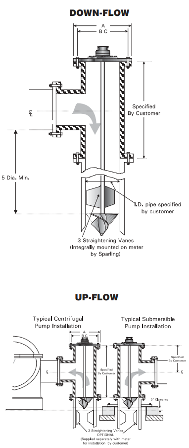
Los medidores Verti-flo se perforan de acuerdo
con los requisitos estándar de 125# o 250# T con
bridas de hierro fundido, como se especifica en el
pedido del cliente, y simplemente se atornillan en
su posición. La longitud de la tubería de bajada
del medidor se fabrica de acuerdo con las
dimensiones generales indicadas en el pedido del
cliente.
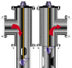
Para instalaciones de flujo descendente, las
paletas de enderezamiento se suministran
integrales con el medidor y no se requieren más
trabajos.
Para flujo ascendente, se recomienda soldar tres
paletas de enderezamiento aguas arriba del
medidor.
Las paletas de soldadura, las paletas de tipo
atornillado y los conjuntos de paleta y
revestimiento de acero inoxidable están
disponibles a un costo adicional.
Materiales
Todos los materiales utilizados en la fabricación
son altamente resistentes a la corrosión normal
del agua y se recomiendan para aplicaciones de
obras hidráulicas Se utilizan materiales especiales
para condiciones altamente corrosivas. La
temperatura del líquido no debe exceder 38°C.
Flujo total
El flujo total acumulado se muestra en un
totalizador de lectura directa de seis dígitos en
cualquier unidad volumétrica estándar
®
INSTRUMENTS, LLC.
Caudales y dimensiones
Tamaño
100mm
6mm
8mm
10mm
12mm
14mm
Flujo estándar
Min
227
379
454
606
757
984
Max
1514
3407
4542
6057
8328
11356
Alto flujo
Min
454
757
908
1211
1514
1968
Max
2271
6057
8706
11356
15142
18927
1034
kPa
A
229
279
343
406
483
533
BC
7
1
2
9
1
2
11
3
4
14
1
4
17
18
3
4
# de tornillos
8
8
8
12
12
12
Tamaño de los
tornillos
5
8
3
4
3
4
7
8
7
8
1
2068
kPa
A
10
13
15
18
21
23
BC
7
7
8
10
5
8
13
15
1
4
17
3
4
20
1
4
# de tornillos
8
12
12
16
16
20
Tamaño de los
tornillos
1
2
3
4
7
8
1
1
1
8
1
1
2
Información sobre pedidos
Tamaño
(mm)
Rango de flujo (LPM)
Longitud del tubo de
caída (mm)
Estándar
Up-Flow
Flujo descen
dente
100
227 - 1510
457
724
6.00
379 - 3410
533
1040
8.00
454 - 4540
584
1350
10.0
606 - 6060
686
1680
12.0
757 - 8330
737
1980
14.0
984 - 11400
864
2310
Cómo pedir un FM132
Tabla 1: BaseModelNumber
FM132
-
Cabezas de medición Verti-flo de accionamiento directo
Tabla 2: Size
04
-
100mm
06
-
6mm
08
-
8mm
10
-
10mm
12
-
12mm
14
-
14mm
Tabla 3: HeadConnections
1
-
125# AWWA Brida (1034 kPa )
2
-
250# AWWA Brida (2068 kPa )
Tabla 4: FlowRange
1
-
Rango estándar
2
-
Alto rango
Tabla 5: Readouts
0
-
Ninguno
Tabla 6: Accessories
0
-
Ninguno
1
-
Paletas de soldadura
2
-
Paletas de atornillar
5
-
Agregar longitud de tubería de
bajada
6
-
Uno y cinco arriba
7
-
Dos y cinco arriba
Modelo
Size
Cabeza
Flujo
Leer
Acceso.
FM132
04
1
1
0
0