®
Especificaciones técnicas
FM182 Magnético
®
INSTRUMENTS, LLC.
Hoja de datos del producto
PDS-FM182-1
2026-07-31
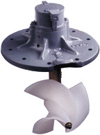
Serie 182 medidores de
transmisión directa
Descripción
Los medidores de transmisión directa de la serie
182 están diseñados para proporcionar
mediciones de flujo precisas y confiables donde se
requiere un servicio de línea principal en áreas
municipales e industriales. Estos medidores se
han utilizado durante más de setenta años y han
demostrado su reputación por ser resistentes y de
servicio continuo con un mantenimiento mínimo.
Este medidor se puede mantener o reparar
fácilmente con herramientas estándar.La
transmisión mecánica por tornillo sin fin y
engranajes es positiva y evita la posibilidad de
deslizamientos y lecturas bajas
El medidor está disponible solo como cabezal de
medidor o como cabezal de medidor completo
con sillín o tubo.
Ver PDS- 110.
Límites de temperatura
Las temperaturas de trabajo del líquido no deben
exceder 38°C. Las hélices pueden almacenarse a
temperaturas del aire de hasta 79°C.
Principio de funcionamiento
Los medidores de hélice Sparling utilizan el
principio simple de la hélice de tornillo para
registrar el flujo total, de la misma manera que un
odómetro registra el kilometraje automático. La
rotación de la hélice proporciona una base para
indicar y registrar galones por minuto o otras
velocidades
Instalación
Los medidores deben instalarse en líneas de
succión o descarga de flujo completo. Evite
válvulas, accesorios o obstrucciones
inmediatamente aguas arriba del medidor que
puedan causar chorros o perfiles de flujo no
simétricos. Se recomienda mantener un mínimo
de cinco diámetros de tubería recta aguas arriba y
un diámetro de tubería aguas abajo del
caudalímetro.
Precisión certificada
La precisión está dentro de 2% del flujo real para
el rango de medidor especificado. Esta precisión
está garantizada por una calibración húmeda
certificada en tres puntos de prueba en el
laboratorio de flujo primario de Sparling trazable
al NIST. Cada medidor se prueba a flujo bajo,
rango medio y flujo alto. Se proporciona un
certificado de prueba con cada medidor.
Rangos de flujo
Estos medidores miden con precisión en un
amplio rango de flujo de 10:1 o más. Los rangos
máximos de flujo se pueden exceder con
seguridad por 50% cuando se usan de forma
intermitente. Los caudales se proporcionan en la
tabla bajo especificaciones para cada uno de los
tamaños
Los rangos de flujo previstos y los índices de flujo
mínimo y normal siempre deben especificarse en
las hojas de aplicación que acompañan a su
pedido.
®
INSTRUMENTS, LLC.
Opciones
Flujos de alta velocidad
- Si el caudal mínimo real excede el caudal mínimo publicado
en la Tabla 1, se requiere una construcción de alta velocidad. Se utilizan hélices y
cojinetes especialmente configurados.
Cuando los índices de flujo continuo exceden el doble del índice de flujo estándar
mínimo en la Tabla 1, se requiere una construcción de alta velocidad.
Los rangos de flujo previstos y los índices de flujo mínimo y normal siempre deben
especificarse en las hojas de aplicación que acompañan a su pedido. Esta información
es necesaria para una evaluación adecuada de la construcción del medidor.
Transmisores
- Hay transmisores electrónicos disponibles para su instalación en estos
medidores.
Ver PDS- 190.
Indicadores de tasa de flujo
- Cuando se requiere una indicación continua de la tasa
de flujo, se encuentra disponible un indicador de tasa de flujo y un totalizador.
Ver
PDS- 190.
Flujos de avance-retroceso
- Hay disponibles tubos especiales para flujos de
avance-retroceso. Estos tubos contienen paletas de enderezamiento tanto aguas
arriba como aguas abajo de la hélice del medidor Se utiliza un totalizador de
avance-retroceso en lugar del registro estándar para totalizar los flujos en ambas
direcciones.
Ver PDS- 190.
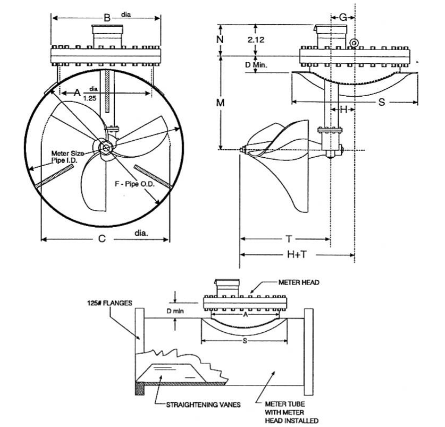
La placa de cubierta del medidor tiene la misma perforación que una brida 150# Clase
D estándar. Este tamaño está indicado por la dimensión " A ".
Las silletas de acero laminado tipo soldadura se suministran para cumplir con el
diámetro exterior de la tubería especificado por el cliente. " M " Drop Pipe se puede
alargar para su uso en tuberías de hormigón o para aplicaciones especiales.
Los medidores se calibran según el diámetro interior de la tubería especificado por el
cliente. Las paletas de enderezamiento deben instalarse inmediatamente aguas arriba
de la hélice para asegurar un flujo recto para una medición precisa
Tamaño
Rango de flujo (LPM)
Estándar
Elevado
16
1325 - 14385
2650 - 25741
18
1703 - 17034
3407 - 30662
20
2082 - 20820
4164 - 37476
24
4542 - 30283
9085 - 57917
30
5678 - 4542
11356 - 81765
36
5678 - 60567
11356 - 109020
42
7949 - 83279
15899 - 151416
48
10221 - 105992
20441 - 189271
54
12870 - 132489
25741 - 238481
60
15899 - 158987
31797 - 287691
66
18927 - 189271
37854 - 340687
72
22712 - 227125
45425 - 416395
Tabla 1: BaseModelNumber
FM182
-
Cabezal de medición de accionamiento magnético básico
Tabla 2: Size
16
-
16mm
18
-
18mm
20
-
20mm
24
-
24mm
30
-
30mm
36
-
36mm
42
-
42mm
48
-
48mm
54
-
54mm
60
-
60mm
66
-
66mm
72
-
72mm
Tabla 3: PressureRating
1
-
1034 kPa
2
-
1724 kPa
Tabla 4: MDimension
1
-
Estándar
6
-
Especial
Tabla 5: FlowRange
1
-
Rango estándar
2
-
Alto rango
Tabla 6: Readouts
0
-
Ninguno
Tabla 7: Accessories
0
-
Ninguno
1
-
Extensión de registro
7
-
Para flujo hacia adelante y hacia atrás
Modelo
Size
Presión
M Dim
Flujo
Readouts
Acceso.
FM182
16
1
1
1
0
0
*
Si el medidor se opera continuamente a flujos por encima del punto medio del rango de flujo estándar, se requieren cojinetes de goma
®
INSTRUMENTS, LLC.
Caudales y dimensiones
Tamaño (mm)
16
18
20
24
30
36
42
48
54
60
66
72
A
406
406
406
406
406
610
610
762
762
762
762
762
B
24
24
24
24
24
32
32
39
39
39
39
39
C
13
16
16
16
16
25
25
38
38
38
38
38
Min. D
102
114
114
114
114
127
127
140
140
140
140
140
F
16
18
20
24
30
36
42
48
54
60
66
72
G
116
116
116
116
116
173
173
249
249
249
249
249
H
108
108
108
108
108
165
165
241
241
241
241
241
M
311
343
368
413
489
584
660
749
826
902
978
1041
N
73
73
73
73
73
80
80
83
83
83
83
83
S
*
660
660
660
660
927
927
1187
1187
1187
1187
1187
T
305
305
305
305
305
476
476
508
508
508
508
508
Círculo de tornillos
540
540
540
540
540
749
749
914
914
914
914
914
Tamaño de los tornillos
1
1
1
1
1
1
1
4
1
1
4
1
1
4
1
1
4
1
1
4
1
1
4
1
1
4
Número de tornillos
16
16
16
16
16
20
20
28
28
28
28
28
*
Peso del metro completo menos paletas enderezadoras
*
La fábrica puede recomendar tarifas y dimensiones para medidores hasta 120mm de tamaño