®
Technical Specifications
FM134
®
INSTRUMENTS, LLC.
Product Data Sheet
PDS-134
2026-07-31
VertiFlo
Vertical Propeller Flow Meter
Description
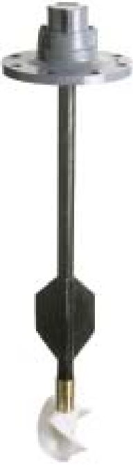
VertiFlo meters provide an economical meter
installation for accurately measuring flows from
wells equipped with submersible pumps.
Equally ideal applications are installations on
the suction side of centrifugal pumps or similar
installations where space limitations and piping
configurations deem it inadvisable to utilize the
Sparling tube-type or conventional saddle type
meters. Special requirements for meter
installation are reduced to a minimum because
the meter is installed in a standard flanged tee.
Certified Accuracy
Accuracy is within 2% of actual flow for the
specified meter range. This accuracy is
guaranteed by certified wet calibration at three
test points in Sparling's NIST traceable primary
flow laboratory. Each meter is tested at low
flow, mid-range, and high flow. A test
certificate is provided with each meter.
Electronic Design
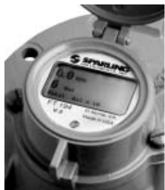
The Model FM134 features the FT194-II battery
powered electronic rate/totalizer which senses
the rotation of the propeller by means of a
magnetic pickup sensor located in the gearbox.
The rate/totalizer and pickup are completely
isolated from the flow stream.
Fewer moving parts combined with a proven
Sparling design relluts in less wear, reduced
maintenace costs and longer life.
Rate Indication and Totalizer
The rate is shown on a 5-digit LCD readout and
the cumulative total flow is shown on a 8-digit
LCD straight reading totalizer in any standard
volumetric units.
The FT194 is ordered separately, it can be
mounted integrally, remotely and with the
outputs: 4-20mA and Pulse Output.
High Velocity Flows
- For applications where
continuous flow rates are above the mid-point
standard flow range ratings, high velocity
construction of the meters is recommended.
Installation
Verti-flo meterheads are drilled in accordance
with standard 125# or 250# cast iron flanged
tee requirements, as specified on customer
order, and are simply bolted into position. The
length of the meter drop pipe is manufactured
in accordance with overall dimensions as stated
in the customer's order.
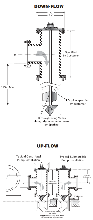
For down-flow installations, the straightening
vanes are supplied integral with the meter and
no further work is required.
For up-flow, three straightening vanes are
recommended to be welded upstream of the
meter.
Welding vanes, bolting type vanes and
stainless-steel liner and vane assemblies are
available at extra cost.
Materials
All materials used in manufacturing are highly
resistant to normal water corrosion and
recommended for water works application.
Special materials are utilized for highly
corrosive conditions. Liquid temperatures
should not exceed 100°F.
®
INSTRUMENTS, LLC.
Flow Rates & Dimensions
Size
4"
6"
8"
10"
12"
14"
Low Flow
Min
50
90
100
125
150
250
Max
400
900
1200
1600
2200
3000
Standard Flow
Min
120
200
240
320
400
520
Max
600
1600
2300
3000
4000
5000
150 psi
A
9
11
13.5
16
19
21
BC
7
1
2
9
1
2
11
3
4
14
1
4
17
18
3
4
# of Bolts
8
8
8
12
12
12
Size of Bolts
5
8
3
4
3
4
7
8
7
8
1
300 psi
A
10
12.5
15
17.5
20.5
23
BC
7
7
8
10
5
8
13
15
1
4
17
3
4
20
1
4
# of Bolts
8
12
12
16
16
20
Size of Bolts
1
2
3
4
7
8
1
1
1
8
1
1
2
Ordering Information
Size (in)
Flow Range (GPM)
Drop Pipe Length (in)
Low
Up-Flow
Down-Flow
4.00
50.0 - 400
18.0
28.5
6.00
90.0 - 900
21.0
41.0
8.00
100 - 1200
23.0
53.0
10.0
125 - 1600
27.0
66.0
12.0
150 - 2200
29.0
78.0
14.0
250 - 3000
34.0
91.0
How to order an FM134
Table 1: BaseModelNumber
FM134
-
Electronic Vertiflo Meterheads
Table 2: Size
04
-
4"
06
-
6"
08
-
8"
10
-
10"
12
-
12"
14
-
14"
Table 3: HeadConnections
1
-
125# AWWA Flange (150 psi )
2
-
250# AWWA Flange (300 psi )
Table 4: Construction
4
-
Up-Flow (Vanes Not Included)
5
-
Down-Flow (Vanes Included)
Table 5: FlowRange
1
-
Low Range
2
-
Standard Range
Table 6: Readouts
0
-
None
Table 7: Accessories
0
-
None
1
-
Welding Vanes
2
-
Bolting Vanes
5
-
Add. Drop Pipe Length
6
-
One and Five Above
7
-
Two and Five Above
Model
Size
Head
Const
Flow
Read
Access.
FM134
04
1
4
1
0
0