®
Technical Specifications
MainLine
®
INSTRUMENTS, LLC.
Product Data Sheet
PDS-104 / 184 / 194-II
2026-07-31
MainLine
Electronic Propeller Meter
FT194-II
Digital Indicator
Description
The MainLine electronic propeller meter was
designed to provide accurate and reliable flow
measurement where main line service is
required in municipal and industrial areas.
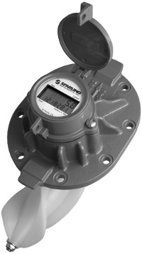
The Model MainLine features the FT194-II
battery powered electronic rate/totalizer which
senses the rotation of the propeller by means
of a magnetic pickup sensor located in the
gearbox. The rate/totalizer and pickup are
completely isolated from the flow stream.
Fewer moving parts combined with a proven
Sparling design relluts in less wear, reduced
maintenace costs and longer life.
The FM104/184 Series II is available with an
optional 4-20mA output for remote
totalizations using either the Sparling Model
787, 710 or the customer's remote totalizer
with 24VDC power supply. Registration can be
changed in the field with the Sparling Model
705 programmer.
Certified Accuracy
Accuracy is within 2% of actual flow for the
specified meter range. This accuracy is
guaranteed by certified wet calibration at three
test points in Sparling's NIST traceable primary
flow laboratory. Each meter is tested at low
flow, mid-range, and high flow. A test
certificate is provided with each meter.
Principle of Operation
Sparling propeller meters utilize the simple
principle of the screw propeller to register the
total flow, much as an odometer registers auto
mileage. The rotation of the propeller affords a
basis for indicating and recording gallons per
minute or other rates.
Applications
MainLine meters are ideal for irrigation, water
well production, pumping stations and golf
course and park water management.
Features
•
Standard ±2% Accuracy
•
Sizes available from 2" - 72"
•
Environmental Rating NEMA 4X
•
Accurately measures over flow range:
10:1
•
8 digit totalizer/indicator
•
Display "sleep mode" conserves
battery life while continuously
totalizing
•
Temporary backup power with 3.6VDC
battery
•
User selectable photocell light
sensitivity from low to bright
Optional Features
•
Remote Mounted Totalizer - up to 50ft
from meterhead
•
Open collector unsealed pulse output
with 12-24VDC loop power.
•
4-20mA Output
Materials
•
Cover Plate: Cast Iron
•
Propeller: Molded Polyethylene
•
Gearbox: Brass up to 30" and Cast Iron
above 30".
•
Bearings: SST or Rubber (High Speed)
•
Coating: Epoxy based paint
®
INSTRUMENTS, LLC.
Installation
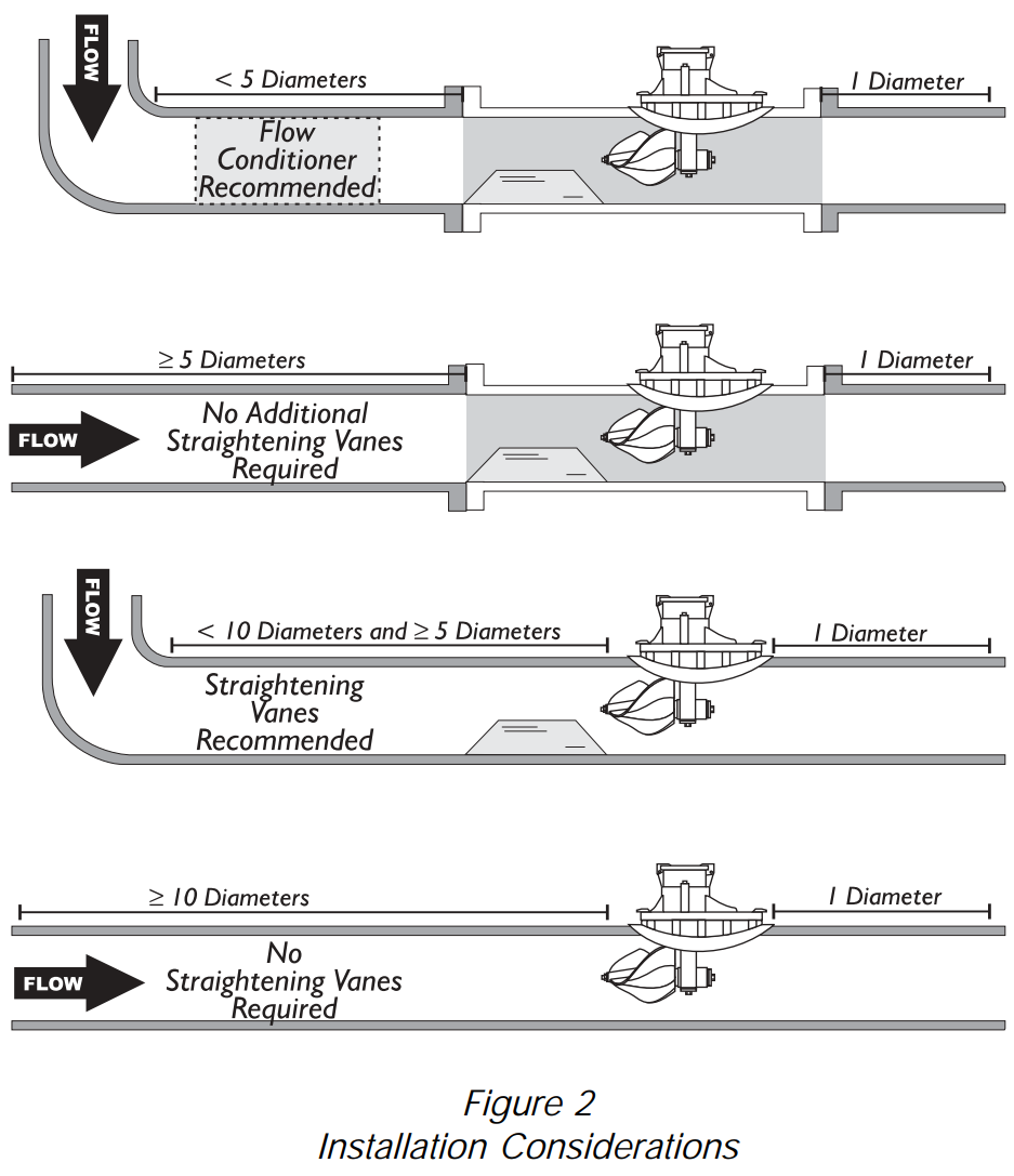
Meters must be installed in full flowing suction or discharge
lines. Avoid valves, fittings or obstructions immediately
upstream of the meter which may cause jetting or
non-symmetrical flow profiles. It is recommended that a
minimum of five straight pipe diameters be maintained
upstream and one diameter downstream of the flow meter.
Temperature Limits
Liquid working temperatures should not exceed 100°F.
Propellers may be stored in air temperatures up to 175°F.
Flow Ranges
These meters measure accurately over a wide flow range of 10:1
or greater. The maximum flow ranges can be safely exceeded by
50% when used intermittently. Flow rates are provided in the
table under specifications for each of the sizes.
Anticipated flow ranges and minimum and normal flow rates
should always be specified on application sheets accompanying
your order.
Easy To Repair
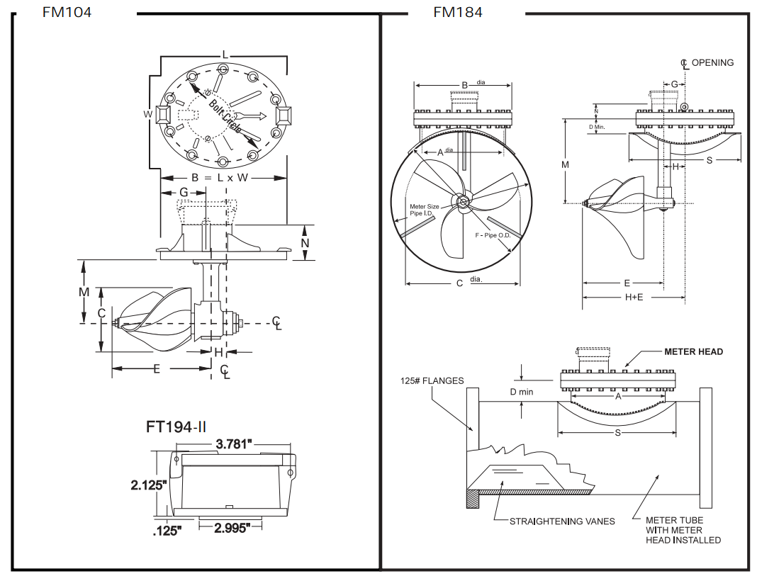
The FM104/184 is easily repaired with common hand tools. No
special tools are required.
Outputs
Optional outputs include Scaled Pulse Outputs (Open Collector)
and 4-20mA.
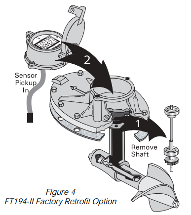
FT194-II Digital Rate/Flow Totalizer
The FT194-II is a digital flow rate and totalizer with an easy to
read LCD display which features simultaneous rate and totalizer
indication. The FT194-II is standard on the FM104/184 but may
also be retrofit to existing Sparling meters see Figure 4.
A non-volatile memory holds all meter parameters such as full
scale, span, calibration factors, engineering units, damping
parameters and flow totals, even in the event of a power failure.
A photoelectric cell activates the display when the cover is
opened. After a user programmed time interval the display
reverts to an energy saving "sleep mode" while continuing to
track total flow. To reactivate the display, simply close and open
the cover. The 3.6VDC lithium battery has 3 years average life. A
low battery indication will display before battery requires
replacement. Low battery display will not affect totalization
accuracy.
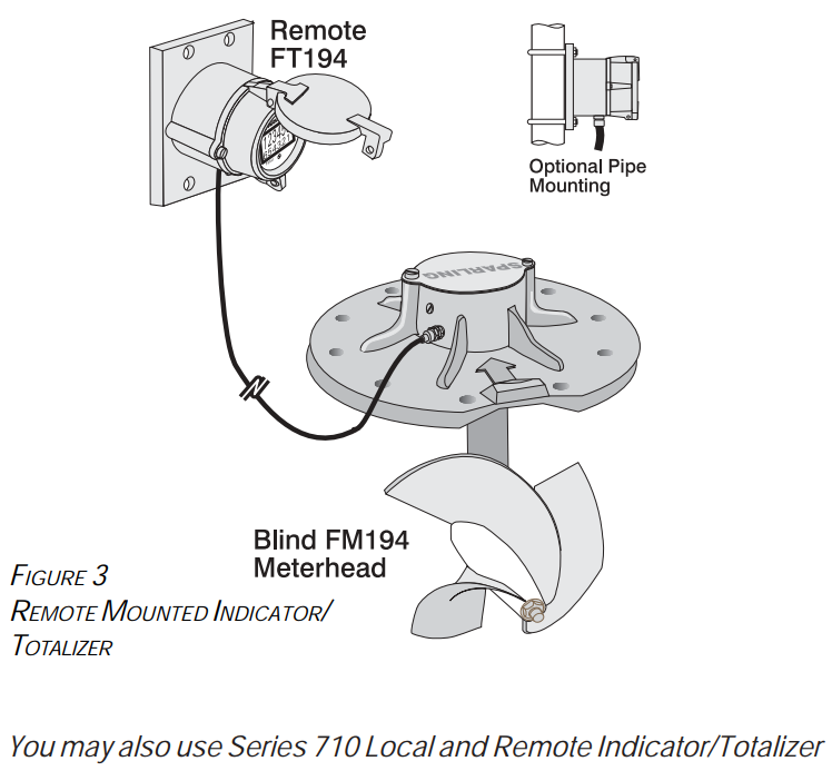
Remote Mounted Transmitter
For remote indication of rate and total the FT194-II
display/transmitter may be mounted up to 50ft from the meter
head. This is ideal for situations where it is inconvenient to have
the indicator mounted integrally to the meterhead, such as a pit
or frequently flooded area. See Figure 3
The remote totalizer is furnished ready to bolt to a wall or
customer supplied plate. Optional U-bolts can be obtained for
pipe mounting. 15ft of cable is supplied standard with the
remote unit. Additional cable may be purchased when the order
is place, up to 50ft.
The optional 4-20mA and Pulse Output require connection to a
customer supplied 24VDC power supply
®
INSTRUMENTS, LLC.
FT194-II RETROFIT AVAILABLE FOR YOUR EXISTING SPARLING
METERS
Sparling's factory technicians can upgrade your existing Sparling
propeller meters to the new FT194-II indicator/totalizer. You'll
have all the benefits of the Model 104/184 Propeller Meter: fewer
moving parts, digital readout and longer life.
Sparling factory technicians remove the vertical shaft and inspect
the propeller shaft, bearings and bushings to insure proper
operation. The magnetic sensor pickup, which is completely
potted and isolated from moisture, is then inserted into the
gearbox and the electronic indicator totalizer is mounted to the
meter body. Finally the meter is wet flow calibrated at a minimum
of three test points.
For detailed metering tube dimensions please visit our website:
www.sparlinginstruments.com
and download
PDS-110
Propeller
Meter Tubes & Saddles.
®
INSTRUMENTS, LLC.
Table 2 - Standard Registration for FT194
Nom. Size
Cubic Feet
U.S. Gallons
Imperial Gallons
Acre Feet
Cubic Meters
Liters
2.0
1.0
10.0
10.0
0.00001
0.01
10.0
3.0
1.0
10.0
10.0
0.0001
0.1
100.0
4.0
10.0
100.0
100.0
0.0001
0.1
100.0
5.0
10.0
100.0
100.0
0.0001
0.1
100.0
6.0
10.0
100.0
100.0
0.001
1.0
100.0
8.0
10.0
100.0
100.0
0.001
1.0
1000.0
10.0
100.0
100.0
100.0
0.001
1.0
1000.0
12.0
100.0
1000.0
1000.0
0.001
1.0
1000.0
14.0
100.0
1000.0
1000.0
0.001
1.0
1000.0
16.0
100.0
1000.0
1000.0
0.01
10.0
10000.0
18.0
100.0
1000.0
1000.0
0.01
10.0
10000.0
20.0
100.0
1000.0
1000.0
0.01
10.0
10000.0
24.0
100.0
1000.0
1000.0
0.01
10.0
10000.0
30.0
1000.0
10000.0
10000.0
0.01
10.0
10000.0
36.0
1000.0
10000.0
10000.0
0.01
10.0
10000.0
42.0
1000.0
10000.0
10000.0
0.01
10.0
10000.0
48.0
1000.0
10000.0
10000.0
0.1
100.0
100000.0
54.0
1000.0
10000.0
10000.0
0.1
100.0
100000.0
60.0
1000.0
10000.0
10000.0
0.1
100.0
100000.0
66.0
1000.0
10000.0
10000.0
0.1
100.0
100000.0
72.0
1000.0
10000.0
10000.0
0.1
100.0
100000.0
How to order a MainLine
Table 1: BaseModelNumber
FM104
-
MainLine Electronic Propeller Meter (2-14")
FM184
-
MainLine Electronic Propeller Meter (16-72")
Table 2: Size
02
-
2"
03
-
3"
04
-
4"
06
-
6"
08
-
8"
10
-
10"
12
-
12"
14
-
14"
16
-
16"
18
-
18"
20
-
20"
24
-
24"
30
-
30"
36
-
36"
42
-
42"
48
-
48"
54
-
54"
60
-
60"
66
-
66"
72
-
72"
Table 3: PressureRating
1
-
150 psi
2
-
250 psi
Table 4: MDimension
1
-
Standard
6
-
Special
Table 5: FlowRange
1
-
Low Range
2
-
Standard Range
Table 6: Readouts
0
-
None
Table 7: Accessories
0
-
None
1
-
Register Extension
Model
Size
Pressure
M Dim
Flow
Read
Access.
FM104
02
1
1
1
0
0
How to order an FT194-II
Table 1: BaseModelNumber
FT194-II
-
FT194-II Digital Rate/Flow Totalizer
Table 2: Outputs
0
-
Display Only, No Outputs
1
-
4-20mA and Pulse Output
Table 3: Mounting
1
-
Integral Mount
2
-
Remote Mount - Wall or Pipe Mount
3
-
Remote Mount - Forward & Reverse
Totalization
Table 4: Options
Calibrator
Programmer
Mounting Hardware (Pipe)
Model
Outputs
Mount
FT194-II
0
1
Available Accessories:
□
Model 705 Programmer
□
Model 704 Calibrator
□
Register Extension
Important: This meter requires a metering tube or saddle to complete installation.
Flow Rates & Dimensions
Size
(in)
Fabr.
Steel
Cast
Iron
A
B
C
D
E
G
H
M
N
S
Flow Range (GPM)
Size of
Bolts
# of
Bolts
150#
250#
150#
250#
Low
Standard
2.00
*
20.0
*
8.13 x 5.13
8.13 x 5.13
2.38
*
4.00
3.13
0.50
1.75
1.75
2.56
*
30.0 - 80.0
60.0 - 150
*
*
3.00
*
20.0
*
8.25 x 6.25
8.25 x 6.25
2.75
*
4.00
3.18
0.63
2.75
2.75
2.56
*
35.0 - 200
70.0 - 360
*
*
4.00
20.0
*
*
9.50 x 6.75
9.50 x 6.75
3.50
*
6.94
4.13
0.63
3.44
3.44
2.56
*
50.0 - 400
120 - 600
*
*
6.00
25.0
*
*
10.4 x 7.31
10.4 x 7.31
4.75
*
6.31
3.69
0.94
4.25
4.25
2.93
*
90.0 - 900
200 - 1600
*
*
8.00
29.0
*
*
11.0 x 10.6
11.0 x 10.6
7.00
*
6.31
5.81
-0.32
5.31
5.31
2.81
*
100 - 1200
240 - 2300
*
*
10.0
34.0
*
*
11.0 x 10.6
11.0 x 10.6
8.00
*
6.31
5.81
-0.32
6.31
6.31
2.81
*
125 - 1600
320 - 3000
*
*
12.0
36.0
*
*
11.0 x 10.6
11.0 x 10.6
10.0
*
6.31
5.81
-0.32
7.31
7.31
2.81
*
150 - 2200
400 - 4000
*
*
14.0
37.0
*
*
11.0 x 10.6
11.0 x 10.6
11.0
*
6.31
5.81
-0.32
8.00
8.00
2.81
*
250 - 3000
520 - 5000
*
*
16.0
210
*
16.0
23.5
25.5
13.0
4.00
12.0
4.56
4.2
12.2
12.2
2.88
*
350 - 3800
700 - 6800
1.00
16.0
18.0
210
*
16.0
23.5
25.5
16.0
4.50
12.0
4.56
4.2
13.2
13.5
2.88
26.0
450 - 4500
900 - 8100
1.00
16.0
20.0
215
*
16.0
23.5
25.5
16.0
4.00
12.0
4.56
4.2
14.2
14.5
2.88
26.0
550 - 5500
1100 - 9900
1.00
16.0
24.0
215
*
16.0
23.5
25.5
16.0
4.50
12.0
4.56
4.2
16.2
16.5
2.88
26.0
800 - 8500
1600 - 15000
1.00
16.0
30.0
220
*
16.0
23.5
25.5
16.0
4.50
12.0
4.56
4.2
19.2
19.5
2.88
26.0
1200 - 12000
3000 - 21600
1.00
16.0
36.0
825
*
24.0
32.0
36.0
25.2
5.00
18.8
6.81
6.5
23.0
24.0
3.13
36.5
1500 - 16000
300 - 28800
1.25
20.0
42.0
835
*
24.0
32.0
36.0
25.2
5.00
18.8
6.81
6.5
26.0
27.0
3.13
36.5
200 - 22000
4200 - 40000
1.25
20.0
48.0
1350
*
30.0
38.8
43.0
25.2
5.50
20.0
9.81
9.5
29.5
30.5
3.25
46.8
2500 - 28000
5400 - 50000
1.25
28.0
54.0
1360
*
30.0
38.8
43.0
25.2
5.50
20.0
9.81
9.5
32.5
33.5
3.25
46.8
3200 - 35000
6800 - 63000
1.25
28.0
60.0
1370
*
30.0
38.8
43.0
25.2
5.50
20.0
9.81
9.5
35.5
36.5
3.25
46.8
4000 - 42000
8400 - 76000
1.25
28.0
66.0
1380
*
30.0
38.8
43.0
25.2
5.50
20.0
9.81
9.5
38.5
39.5
3.25
46.8
4750 - 50000
10000 - 90000
1.25
28.0
72.0
1390
*
30.0
38.8
43.0
25.2
5.50
20.0
9.81
9.2
41.5
42.5
3.25
46.8
5500 - 60000
12000 - 110000
1.25
28.0
The maximum flow ranges can be safely exceeded by 50% when used intermittently. Your Sparling meter utilizes specially designed propellers and bearings matched to your
flow range to insure long life.
Anticipated flow ranges and minimum and normal flow rates should always be specified on application sheets accompanying your order.